• Hello MLAers! We've re-enabled auto-approval for accounts. If you are still waiting on account approval, please check this thread for more information.

Baby's first PCB

luRaichu

6502
I thought I'd get myself to learn PCB design by modifying Bolle's MicroMac Performer clone to remove the PDS slot and Classic CPU socket, thereby specializing the upgrade for a Macintosh Plus only.
Screenshot_2025-11-07_11-03-41.png
I started from this repository which has several KiCad projects you can just open right up: https://github.com/alxlab-zone66x/Performer-SE-PL-CL
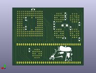
Without knowing anything about anything I simply removed the unneeded parts from the schematic and changed some footprints. Then laid everything out from scratch.
Since I don't know anything about anything I loosely copied the original Performer layout.
 
This is a really good way to learn this stuff - take something that works, fiddle with it a bit so it meets your needs, then see if it still works. Then keep fiddling. Hope you had fun with this one!
 
Thanks for sharing that :) I would instantly throw away all my "work" and just get that PCB made but I refuse to surface mount solder PLCC sockets
I already tweaked my board's layout again to the point where an autorouter can complete it
Screenshot_2025-11-08_09-56-01.png
 
Last edited:
It looks like you could make it much smaller if you wanted. What hardware/software are you using to make edits?

Have fun with the project!
 
It looks like you could make it much smaller if you wanted. What hardware/software are you using to make edits?
I've just jumped right in to KiCad without sitting down and learning anything about it for any significant amount of time
 
Smaller, and thinner with QFP package CPU would be sweeet =) I like socketless
My board is intended to be easy to assemble, without having to solder dense surface mount packages. If you want QFP I'd say do it yourself, if I can do what I've done here then you can too.

What is this pattern called?
Screenshot_2025-11-09_16-46-42.png
I want to attach a via to the ground plane like these holes have been automatically but I can't figure it out

What function do the capacitors serve on the original Performer board?
You can see from the Performer schematic that all capacitors sit between Vcc and ground, so I assume they are for decoupling? They're also almost always sharing a Vcc trace between many resistors
 
Last edited:
I don't know kicad, but those kinds of partial separation between pins and a copper sheet are often called "thermals." The purpose is to make it easier to solder the pin. You probably don't need them for vias. Maybe look for that term in the documentation, or "isolation"?
 
I believed this was because the scrollbar position is calculated as a fractional value representing the amount of the window size visible to the total content height.
Please educate me if i'm wrong, this of course might be a myth that i learnt when i was a little young Joopmac back in the days...
 
I was surprised about that too. Just to clarify the actual operation, it calls SANE for the FP calculations, and SANE will use the FPU if it's available. The things you find debugging emulation.
 
Iteration #2... FPU socket has been erased. Still need to fix some bugs in the silkscreen and via placement in order to pass DRC but this is basically what the finished board should look like. JLCPCB will mint 5 of these for $7.

Is there a guide for avoiding fake 68030s?
 

Attachments

  • polyphloisboisterous030.jpg
    polyphloisboisterous030.jpg
    164.6 KB · Views: 24
  • polyphloisboisterous030-2.jpg
    polyphloisboisterous030-2.jpg
    149.4 KB · Views: 24
We know GAL 7 is a clock doubler, but can it be modified to be a clock quadrupler?
A stock Plus runs at 8MHz, so times four that's 32MHz
 
Back
Top