Hi,
A while ago I acquired a Color Display M1212 in pretty decent cosmetic condition. Unfortunately, the display's image was not always very sharp and would occasionally flicker or turn on and off by itself. The degaussing was also very loud when powering on the monitor. Since I have some experience reparing vintage power supplies and have successfully recapped all my vintage macs before, I decided I would try to recap the CRT control board in an attempt to fix the issue.
After replacing all electrolytic capacitors with high quality Nichicon and Rubicon replacements from Mouser, I am unable to see any picture showing up on the CRT. The CRT does turn on (LED goes green), but I see no picture and also no static on the screen and no visible glow from the "neck" of the CRT tube.
After doing some serious ChatGPT-ing, I was able to isolate the problem to faulty or missing Horizontal output. According to sources in the web, the monitor will refuse to turn on if it doesn't receive any Horizontal output signal. I am not a CRT expert and cannot be sure that this is accurate, so after days of getting nowhere I am requesting the support from the community to try and solve the issue.
What I have verified so far:
- All capacitors are of right value and have been placed in the right orientation
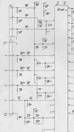
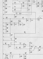
- I checked the soldering joints are solid by verifying continuity (I used this schematics: https://usermanual.wiki/Document/AppleM1212MonitorSchematic.2035905086/view)
- I checked voltage at the H.O.T and got 118V at the Colector and 0V at the Base (according to sources, Base should not be 0V)
- I am hooking up the monitor to a known good machine
Also, I found that there is a 4.7KOhm resistor soldered to PIN 39 of the Jungle IC and leading up to jumper (see picture below). I have another one of these monitors, which I opened up and oddly I don't see it on the other monitor. Im not sure this is stock and was probably added during some repair work in the past?
Any help saving this monitor or a tip that could lead me in the right direction would be very much appreciated.


Capacitor list: https://tinkerdifferent.com/resources/macintosh-color-display-m1212-capacitor-list-1-645-346-13.25/
Schematics: https://usermanual.wiki/Document/AppleM1212MonitorSchematic.2035905086/view


A while ago I acquired a Color Display M1212 in pretty decent cosmetic condition. Unfortunately, the display's image was not always very sharp and would occasionally flicker or turn on and off by itself. The degaussing was also very loud when powering on the monitor. Since I have some experience reparing vintage power supplies and have successfully recapped all my vintage macs before, I decided I would try to recap the CRT control board in an attempt to fix the issue.
After replacing all electrolytic capacitors with high quality Nichicon and Rubicon replacements from Mouser, I am unable to see any picture showing up on the CRT. The CRT does turn on (LED goes green), but I see no picture and also no static on the screen and no visible glow from the "neck" of the CRT tube.
After doing some serious ChatGPT-ing, I was able to isolate the problem to faulty or missing Horizontal output. According to sources in the web, the monitor will refuse to turn on if it doesn't receive any Horizontal output signal. I am not a CRT expert and cannot be sure that this is accurate, so after days of getting nowhere I am requesting the support from the community to try and solve the issue.
What I have verified so far:
- All capacitors are of right value and have been placed in the right orientation
- I checked the soldering joints are solid by verifying continuity (I used this schematics: https://usermanual.wiki/Document/AppleM1212MonitorSchematic.2035905086/view)
- I checked voltage at the H.O.T and got 118V at the Colector and 0V at the Base (according to sources, Base should not be 0V)
- I am hooking up the monitor to a known good machine
Also, I found that there is a 4.7KOhm resistor soldered to PIN 39 of the Jungle IC and leading up to jumper (see picture below). I have another one of these monitors, which I opened up and oddly I don't see it on the other monitor. Im not sure this is stock and was probably added during some repair work in the past?
Any help saving this monitor or a tip that could lead me in the right direction would be very much appreciated.
Capacitor list: https://tinkerdifferent.com/resources/macintosh-color-display-m1212-capacitor-list-1-645-346-13.25/
Schematics: https://usermanual.wiki/Document/AppleM1212MonitorSchematic.2035905086/view