
This is a great hack for building all kinds of DIY rack mounted projects on the cheap! Thanks for sharing!Aha, the trick to this, I have discovered, is to get a crappy 48-port switch that nobody wants off eBay. Something like an HPE one, you know - the kind of thing that hangs around on eBay for months then goes to recycling. They're in decent cases and the 48 ports means they already have a huge hole in the front that's a really handy size for stuff.
I got this one for a tenner: I didn't want the switch, but I got a 1U rack case, a 12/5V dual PSU and 14 decent heatsinks for that tenner, which counts as a bargain as far as I'm concerned. This is hugely better value than getting a new 1U project case, which will be more expensive, not have a big hole in the front, and will probably (IME) be worse quality.
They also tend to have LEDs and management ports that can be repurposed for fun. That's the plan here.
-
 Hello Guest! We're hosting a challenge to welcome vintage Intel macs to the MLA during the month of July! See this thread for more information.
 -
We've made some quality of life improvements to the Trading Post. More info here.
You are using an out of date browser. It may not display this or other websites correctly.
You should upgrade or use an alternative browser.
You should upgrade or use an alternative browser.
A thread for RackMacs
- Thread starter cheesestraws
- Start date
@cheesestraws That front label looks great — is it an adhesive sticker thing or some kind of print on plastic?

is it an adhesive sticker thing or some kind of print on plastic?
It's actually a PCB - unless one actually owns a laser cutter, that seems to be the most cost-effective way of getting 'a custom shaped sheet of something with holes in and printing on' at the moment, then just glued on the front with latex glue so it's removable. This seems rather silly, but economics of scale and the rather brutal competition among the low-end Chinese PCB manufacturers are probably what's at play. It probably will stop being true at some point.
What's the 2nd RJ45 port for?
I'm hooking up an ESP32 to the reset line and some diagnostics so I can query them remotely (e.g. is the fan still running).
Here's a test fit photo from yesterday: the blue PCB is the monitoring/reset circuitry, and the ethernet link goes over that ribbon cable to the front panel along with the LEDs.

Last edited:
This could be from 1998 Apple..

Attachments
nah, it would probably be more like HPE's ILOiDRAC for the Mac LC, love it


WOW! What did that 1U PCB frontspiece cost? Stock panel size? Something like that for my 2UBG3 would be perfect.It's actually a PCB - unless one actually owns a laser cutter, that seems to be the most cost-effective way of getting 'a custom shaped sheet of something with holes in and printing on' at the moment, then just glued on the front with latex glue so it's removable. This seems rather silly, but economics of scale and the rather brutal competition among the low-end Chinese PCB manufacturers are probably what's at play. It probably will stop being true at some point.
Even better if some circuitry might be implemented on the board, power indicator, disk access LEDs and other stuff.
")
edit: I've got a few DA15M IDC connectors on hand - put thruholes for an IDC socket - feed Mac Video out to the PCB with DIP switches/circuitry for VGA Conversion - add soldertail HD15 - Bob's your uncle!
Last edited:
WOW! What did that 1U PCB frontspiece cost?
About £8 + shipping from JLCPCB (for 5 - minimum order). Other PCB manufacturers are available, of course. And yes, you could easily add some electronics to one side of it - it's a PCB, after all. I don't know what you mean by "stock panel size"?
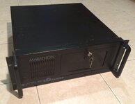
My Marathon GRack Quicksilver is in storage so here’s a pic I store from macrumors. I think is is actually a Digital Audio but the case is the same.
These are cool. I love how chunky and serious they look :-D.
Last edited:
Some more progress photos. I've got to mount the speaker and rescue the PSU from the old rack case, and there's still some software missing on the LCBMC. But on the whole I think this is nearly finished and will be able to replace the old case before it disintegrates. Hooray.
The ZuluSCSI is on little feet at the back, which means that the SD card slot is available over the back of the case. This is something I learned the hard way from the first iteration: make it so you can get the SD card out without having to take the whole lot to bits.


The ZuluSCSI is on little feet at the back, which means that the SD card slot is available over the back of the case. This is something I learned the hard way from the first iteration: make it so you can get the SD card out without having to take the whole lot to bits.
@cheesestraws That is absolutely amazing work there.
Yep, very cool. By stock panel size, I'm thinking about the limitations of the 10cm x 10cm SEEED square everything seemed to have been based upon a few years back. That's a pretty wide PCB, if thin.
I don't see anything on the JLPCB about panel size specifications. One day I need to start laying boards out to bring my projects into the real world.
I don't see anything on the JLPCB about panel size specifications. One day I need to start laying boards out to bring my projects into the real world.
And that, I think, will do.


Absolutely amazing work on this! I wish this was a commercial product as a replacement case for LCs!
Absolutely amazing work on this! I wish this was a commercial product as a replacement case for LCs!
If it'd be any use, I can make the front panel PCB design available? The rest of the case is a switch that comes up on eBay pretty often.
I love the fact that you left the HP sticker intact, lol.
Nobody's looking at the back, not even me
 The main problem is I seem to have lost several of the screws. Hrm...
That'd be appreciatedIf it'd be any use, I can make the front panel PCB design available? The rest of the case is a switch that comes up on eBay pretty often.
Similar threads
- Replies
- 10
- Views
- 3K
- Replies
- 575
- Views
- 191K
- Replies
- 115
- Views
- 32K