
• Hello Guest! We're hosting a challenge to welcome vintage Intel macs to the MLA during the month of July! See this thread for more information.
  • We've made some quality of life improvements to the Trading Post. More info here.

3D printable iMac G3 replacement screen bezel

Hi all,
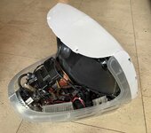
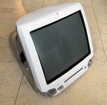
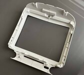
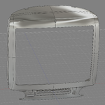
I recently worked on a 3D printable replacement inner bezel for the iMac G3. I think it fits quite well now, so the CAD and STL files have been released:

Github link

Thingiverse link

For the printing material I recommend ABS or ASA. Viability of PETG is still under investigation due to the temperatures it needs to withstand.

It's a work in progress, and I currently tested this only using my own printer. If you decide to give this 3D printed bezel a shot, feedback is appreciated.
 

Attachments

  • CAD_Front.png
    CAD_Front.png
    413.1 KB · Views: 13
  • pic2.jpg
    pic2.jpg
    1.9 MB · Views: 12
  • Print_Assembled.jpg
    Print_Assembled.jpg
    821.3 KB · Views: 13
  • Print_Back.jpeg
    Print_Back.jpeg
    711.8 KB · Views: 13
Wow — did you scan it as a basis? How did you manage the accurate dimensions?
Mostly by taking pictures of the curves where it had to fit, using caliper measurements on the original bezel (I had the chance of having an intact one) and quite some trial and error.
I don’t have access to a 3D scanner, unfortunately.
 
Mostly by taking pictures of the curves where it had to fit, using caliper measurements on the original bezel (I had the chance of having an intact one) and quite some trial and error.
I don’t have access to a 3D scanner, unfortunately.
Nice work. Have you tried Photogrammetry as a starting point for complex shapes? Painting a texture on it might help with that as the uniform colour and texture will make it harder to get good results.
 
How do the four pieces stick together and does it matter with respect to rigidity? I seem to remember the bezel was a structural part.
There are glues stronger than the 3D printed parts. This is one place the rough surface of the prints help, although I'd probably still run some rough sand paper over it.

Plexus MA 300 might work well for something like this? You'd almost certainly delaminate the part before you broke the bond.
 
Another option is to use the 3D printed part as a pattern to cast a part in resin or even possibly metal, although I'm not sure if you could get these to come out of a flexible silicone mould, and I'm not sure if it would be possible to get the print out of a green sand mould or similar.

It would be awesome to cast an aluminium bezel! Although you'd have to increase the size of the print to compensate for shrinkage.
 
Last edited:
Nice work. Have you tried Photogrammetry as a starting point for complex shapes? Painting a texture on it might help with that as the uniform colour and texture will make it harder to get good results.
Yes I tried Polycam initially but quickly lost patience with it. Didn’t try to paint a texture on the original bezel though.

How do the four pieces stick together and does it matter with respect to rigidity? I seem to remember the bezel was a structural part.
You’re right, this a structural part. You can see my model has a lot more larger volumes for that reason. There are four large dowels connecting everything together. Additionally, when you print in ASA or ABS, you can/should use acetone to weld everything together.

But trust me, when you just insert the dowels and screw the CRT onto the bezel, the structure is already very rigid without any glue (and can’t fall apart). I still recommend to glue/weld it though for optimal results, even it’s only to hide the seams – acetone is very good at this.
 
Didn’t try to paint a texture on the original bezel though.
We've had issues with large flat surfaces in the past. We put some lines on the surface with electrical tape to help (larger scale), but anything to add variation that the software can recognise would help.

It's still only going to be a reference though, generally taking measurements for a critical dimension is going to be best.

Do you have access to a CNC router with a large bed? To get the compound curves you could cover the surface in a conductive spray paint, clip on a wire and then use an CNC tool to poke the surface as a probe (I used to just clip another crocodile clip onto an engraving tool - a ball mill would probably be kinder to the part). Much slower than using a fancy proper probe, but by detecting the complete circuit you can create a heigh map of a complex surface. Obviously no underhangs and your resolution is limited by how long it takes, and there is the risk of smashing the bezel if the circuit fails to complete or the clip falls off 😆 I used to do something similar to map the surface of cheap PCB material I was routing.
 
Do you have access to a CNC router with a large bed? To get the compound curves you could cover the surface in a conductive spray paint, clip on a wire and then use an CNC tool to poke the surface as a probe
I initially thought of sacrificing my bezel by cutting it in 4 and use my 3D printer to probe it. It would have been a shame to destroy an otherwise intact bezel for that though. But yes, the idea is the same indeed.
 
I initially thought of sacrificing my bezel by cutting it in 4 and use my 3D printer to probe it. It would have been a shame to destroy an otherwise intact bezel for that though. But yes, the idea is the same indeed.
Yeah, I'd feel uncomfortable sacrificing a bezel in case I didn't manage to finish the project.

Another idea for strength - I've not heard anyone doing it with 3D prints, but you know the metallic plated finish you see on some injection moulded parts? That is actually in part done for strength. Plating tends to be tricky to get right, but I wonder could you do something similar with a thin coat of lacquer?

The old joke that a rusty old car with a fancy paint job gets all its strength from the paint and there is no metal left underneath.

Although I m just rambling and the print is probably plenty strong enough as it is, especially as you've bulked it up.
 
Another idea for strength - I've not heard anyone doing it with 3D prints, but you know the metallic plated finish you see on some injection moulded parts? That is actually in part done for strength.
Didn’t know that. I know you can improve the strength of ABS or ASA prints further by vapor smoothing with acetone as it fuses the outer layer lines together into a single continuous shell.
Although I m just rambling and the print is probably plenty strong enough as it is, especially as you've bulked it up.
I’m quite confident it’s more than strong enough without post-processing. The first point of failure I can imagine are the holes/threads of the CRT screws, as the screen ‘pulls’ on those and may cause delamination. However, these screws are quite long and have a large thread, so this is unlikely unless you have a incorrectly tuned printer causing low layer adhesion.

I also tried to mitigate this by getting rid of all thin/constant thickness features usually seen on injection molded parts. I don’t know if that was one of the reasons why previous 3D printing attempts by other people may have failed.
 
I also tried to mitigate this by getting rid of all thin/constant thickness features usually seen on injection molded parts. I don’t know if that was one of the reasons why previous 3D printing attempts by other people may have failed.
I don't think there has been a previous attempt.

The referenced incident didn't get off the ground. The person in question was asking for MacEffect's CAD models and didn't get them. Looking at their profile they never posted on any other threads and while they said they were going to scan one, there weren't any updates.
 
Back
Top