• Updated 2023-07-12: Hello, Guest! Welcome back, and be sure to check out this follow-up post about our outage a week or so ago.

SE30 new board with Simasimac

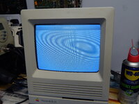
I've recently been sent a new SE30 board, built by someone else but its throwing the below screen which I understand is the simasimac problem. Reading this forum and other places I understand it that this is typically down to something in the data path between the rom simm, cpu, glue chip or ram simms. The board has been built with all new passives but everything else is recovered. The rom simm and the ram all test good in another SE30 board. I've been told the entire chipset has been previously tested in another board and is good, I can't really test this myself since the other SE30 board isn't socketed.

Unfortunately I have no means of powering the board outside of the case so its looking like its going to be a bit of hit or miss testing to find the culprit here. Considering this is a new board I don't foresee and trace damage, could the 258s cause this issue?

Photo of the simasimac screen
DSCN4442.JPG

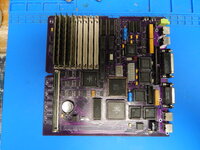
Photo of the board, apologies for the glare.
DSCN4443.JPG
 
The replacement board is this one - https://github.com/TheRealBolle/SE30
I noticed on the bottom of it adjacent to the position for the optional rom chips (instead of romsimm) there are 2 jumper pads. Does anyone know if these need to be set any particular way when using the romsimm? There is no mention of them in the github, or none that I can find anyway.

@joshc I see from the github you wrote the BOM for this board. Do you know if these jumper pads needs set?
 
Last edited:

zigzagjoe

Well-known member
Oh, that is likely to be fun. I'd think you'd want to start testing from first principles....
  • check that RESET line works correctly
  • check that there's a clock signal
  • check that address and data lines aren't bridged somewhere
  • probably start toning the buses out from the RAM/ROM slots to the PDS slot?
 

zigzagjoe

Well-known member
Unfortunately I have no means of powering the board outside of the case so its looking like its going to be a bit of hit or miss testing to find the culprit here.
By the by - you can use a 24 pin ATX extension cable to give you a bit of breathing room for troubleshooting. You don't even have to modify it. That and a spare speaker works wonders when you need to check signals on a running board.
 
By the by - you can use a 24 pin ATX extension cable to give you a bit of breathing room for troubleshooting. You don't even have to modify it. That and a spare speaker works wonders when you need to check signals on a running board.
Thanks for the tip, that will come in very handy cause I was wondering how to power this out of the case.

In terms of the other things you suggested to try, yes I will check all that but I expect if there is a picture being generated then we must at least be coming out of reset and must have a clock. I've looked over the entire board and I don't see anything bridged but thats not to say there isn't something I haven't seen.

I'll hopefully be able to do some more testing this evening.

This might be a stupid question but the board designed by TheRealBolle on github, I assume it is a tested working board and other people have successfully built it?
 

Bolle

Well-known member
assume it is a tested working board and other people have successfully built it?
Yes, it is:
 
Yes, it is:
Thanks, I was sure it would be but not being that familiar with Mac stuff I thought it at least worth checking. I'm not sure if you've read all this thread but I previously asked about the jumper pads on the bottom adjacent to the rom sockets. Do these need set one way or the other if I'm using a rom simm?
 

Bolle

Well-known member
That's not going to be your problem, but I noticed you have two crystal oscillators installed for the ASC. It's definitely not going to produce any sound that way. I'd make sure those are not damaged from running in parallel further down the road (or just take them both off and put a single new one back on)

I don't recommend to use sockets at all for the large PLCC chips. The chips very likely would have to be prepared to make good contact... remove corrosion, clean off any flux from desoldering them, possibly re-tin them if they've been sitting in cap goo on the donor board for ages.
If you want to rule out any contact issues with the sockets get a tiny probe and verify all connections to the socketed chips from the actual legs to wherever that signal goes according to the schematics.

I previously asked about the jumper pads on the bottom adjacent to the rom sockets. Do these need set one way or the other if I'm using a rom simm?
No need to touch them at all when using a ROM SIMM.
 
That's not going to be your problem, but I noticed you have two crystal oscillators installed for the ASC. It's definitely not going to produce any sound that way. I'd make sure those are not damaged from running in parallel further down the road (or just take them both off and put a single new one back on)

I don't recommend to use sockets at all for the large PLCC chips. The chips very likely would have to be prepared to make good contact... remove corrosion, clean off any flux from desoldering them, possibly re-tin them if they've been sitting in cap goo on the donor board for ages.
If you want to rule out any contact issues with the sockets get a tiny probe and verify all connections to the socketed chips from the actual legs to wherever that signal goes according to the schematics.


No need to touch them at all when using a ROM SIMM.
Thanks for the tip, I'll replace both of those crystals with a single one!

As I say I didn't build this board. I'm not sure why the original builder went with mostly all sockets, I probably wouldn't have done that myself either to be honest. I'll ask them if they are happy for me to remove the sockets and solder the ICs directly.
 
Well I got it sorted. Reflowed all SMD work and refinished the pins on all PLCC chips, chimed and booted straight away :)

Or well more or less, I managed to damage a ram simm in the process but thats glued now and the boards working fine.

Just in case anyone is interested -
 

zigzagjoe

Well-known member
Congrats! Bummer about the broken clip. I really need to redo sockets on mine also, but an interim trick for one or two broken SIMM clips is to use a 3d-printed spacer to have the SIMM behind/in front apply a little pressure to help the broken side.

How much "fun" did you find removing the eurodin connector? At some point, I want to get an asante maccon and stick a right angle connector on it, but I don't fancy the level of effort involved in removing it.

1684768934883.png
 
I assume you mean the pds slot? It was a bit of a nightmare to get off to be honest. It took a lot of heat and the desoldering station to get most pins released but several just would not let go. I had no choice in the end but to pull of the connector leaving a few pins on the board then desolder them separately and refit them to the slot. There was heavy corrosion under it which caused the problems. I gave it a bath in white vinegar then IPA before fitting to the new board, it looks ok now although is a bit tainted from the amount of heat required.

If you skip towards the end of the video you'll see it, it's chaptered to make it easier to find.

But speaking of said slot... Is there anywhere I can buy one? I've done a deal with the guy who owns the board I repaired and I've bought the second chipset and what's left of the green PCB to build the purple board he gave me. But I'm missing a pds slot and I'll also need a ROM simm.

Is there anywhere you guys would recommend getting those parts?
 

zigzagjoe

Well-known member
I assume you mean the pds slot? It was a bit of a nightmare to get off to be honest. It took a lot of heat and the desoldering station to get most pins released but several just would not let go. I had no choice in the end but to pull of the connector leaving a few pins on the board then desolder them separately and refit them to the slot. There was heavy corrosion under it which caused the problems. I gave it a bath in white vinegar then IPA before fitting to the new board, it looks ok now although is a bit tainted from the amount of heat required.

If you skip towards the end of the video you'll see it, it's chaptered to make it easier to find.

But speaking of said slot... Is there anywhere I can buy one? I've done a deal with the guy who owns the board I repaired and I've bought the second chipset and what's left of the green PCB to build the purple board he gave me. But I'm missing a pds slot and I'll also need a ROM simm.

Is there anywhere you guys would recommend getting those parts?
Yes, sorry, the PDS slot. I saw the video and it looked pretty much as bad as I figured it would be. My big concern is not cooking the board in the process. I've got all the kit, but it is undoubtedly the worst thing on the board to need to remove.

Purchasing new ones isn't too bad. DIN/euroDIN 41612, 120 positions, 3 rows, female.

This should be the correct type: https://www.digikey.com/en/products/detail/te-connectivity-amp-connectors/535098-5/146336
 

falen6

Well-known member
Where did you get that purple se/30 board ? - are they for sale anywhere ? - i have 3 se/30's with battery damage
 
Top