• Updated 2023-07-12: Hello, Guest! Welcome back, and be sure to check out this follow-up post about our outage a week or so ago.

SE/30 Restoration Fun

chu-oh

Well-known member
You know you can swap out the yokes right? The tube itself is identical. 


Orly? I was under the impression from this: 


That they weren't compatible.

So if I can swap the analog board connector headers and use the se30 yoke (that's hopefully not damaged) I should be right?


BadGoldEagle

Well-known member
The types @Scott Baret mentions only apply to the yoke.

I've once swapped a "type B" CRT from a Classic II in a "type A" Classic. Just replace the yoke and re-do the adjustments. The neck arrangement is also pretty much standard, given that you can also use green/amber phosphor 9" from other manufacturers. 


chu-oh

Well-known member
The types @Scott Baret mentions only apply to the yoke.

I've once swapped a "type B" CRT from a Classic II in a "type A" Classic. Just replace the yoke and re-do the adjustments. The neck arrangement is also pretty much standard, given that you can also use green/amber phosphor 9" from other manufacturers. 


Oh that changes everything. 

So how did you handle the different analog board connections? Is it possible to use the staple trick to get the pin headers out and swap the sockets?


BadGoldEagle

Well-known member
I didn't touch the connector, I don't know those CRTs well enough to play around with the pinout. I simply removed the yoke altogether on both CRTs, taking note which way the connector was pointing (roughly), and reinstalled the one that goes with the analog board on the good CRT.

Some info on how to take it out (there's only one screw to loosen, try with the dead CRT first) 

https://oldcrap.org/2019/05/03/inside-macintosh-crt/

The part relevant for you:

First you will need to remove the tube from the case and disconnect it from the analog board. This is the dangerous part of the job, because the tube will likely contain an electrical charge. You need to discharge it prior to removing the flyback electrode. There is a good video about it and it really works.

To disassemble a Macintosh CRT, first start with removing the deflection yoke. It is very easy, unscrew the ring screw and gently pull the yoke from the CRT. Yoke’s purpose is to scan the electron beam over the screen horizontally and vertically.


Then there's the adjustment. You shouldn't have to twist any of the magnets (only if the display is not rectangular, do it last if that's the case). 

The deflection yoke can be rotated or moved forward/back. If available, I'd place the Mac on a glass table facing down (that way you won't have to deal with the forward/backward adjustment). Don't tighten the screw all the way, plug everything back, and turn it on. If the display is tilted, turn it back off, wait a bit, and gently rotate the yoke accordingly. You could also do it while powered on, but if it's your first time, I wouldn't risk it. Just take your time!

Also, that screw tightens the collar, so don't tighten it too much, just so that it won't move or you'll break the CRT's neck!

 

techknight

Well-known member
Ive done a youtube video years ago swapping CRTs around outlining the yoke issue. 

Basically, its a non-issue. All the black and white CRTs of that era have identical pinouts, and electrical specifications that are fairly similar for the 9" size. Only differences being the bolt pattern and anode lead location whether right or left side. (between different CRTs)


chu-oh

Well-known member
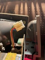
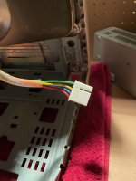
These are the different header types I'm talking about.

Anyone have any ideas on a trick to remove the headers so attach the crt to the SE30 analog board? I've tried the old staple trick but it didn't work. 

I know I could simply snip and solder them but I'd prefer to be less destructive. 

IMG_0141.jpeg

IMG_0142.jpeg


Daniël

Well-known member
The connector is attached to the yoke, if you swap the yokes across the two tubes this should no longer be an issue.

 
Last edited by a moderator:

chu-oh

Well-known member
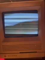
I don't think I've seen that particular kind of distortion on a Compact before!


It was happening with the old CRT too - it's solved by adjusting the crt anode cap, making it taut seems to fix it. 

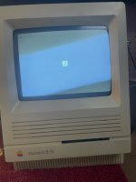
So I've played around with the yoke adjustment but I'm struggling to get it better than this (it's sitting towards the right).

Do I need to adjust more or is this a geometry issue?

IMG_0178.jpeg


chu-oh

Well-known member
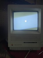
Tweaked the geometry a bit - better but still not perfect. Will play around with it a bit more later.

51F1E879-268B-4B5D-88F5-93C422D95AE7_1_105_c.jpeg


chu-oh

Well-known member
Thanks mate, it's getting there. It's got the tinsiest bit of burn in but I reckon I can live with it. 

I've still got the issue with sound only coming out of the headphone jack now (this was occuring before the CRT replacement). I reckon this is something to do with grounding because it's stopped a few times when I've moved the psu around. I've noticed my Astec psu doesn't have the grounding wire to the chasis like this one https://preview.redd.it/a3acpkra0nm11.jpg?width=640&crop=smart&auto=webp&s=1449680db1835e66bb1f7d193e16a9c4b8075bb3 - I don't know if that is just a feature of the Sony PSUs or I'm missing something. 

Regardless the psu and analog board need a recap anyway. 


aeberbach

Well-known member
I have the Astec and the ground wire is definitely present. Any chance the switching function of the headphone jack has become sticky and the machine always detects a jack inserted? If you remove the headphone jack and test that might tell you.

 
Top