• Updated 2023-07-12: Hello, Guest! Welcome back, and be sure to check out this follow-up post about our outage a week or so ago.

SE/30 Daystar P33 weirdness

apm

Well-known member
I've been trying to get a Daystar P33 accelerator (50MHz 68030) working in an SE/30 with one of @Bolle's amazing adapters -- in this case the model from the early 2020, short form factor with Asante ethernet card underneath.

The P33 itself is faulty in some odd ways which I'm trying to figure out. Thanks to @james_w we've been able to make comparisons between this P33 and another known-good P33, and also between my Bolle-adapter and the earlier "tall" type Bolle-adapter that James has.

The SE/30 runs with the P33 inserted, but it locks solid when you try to open the Power Central control panel in the Finder. Loading Power Central at boot also locks the machine if and only if the P33 cache is enabled. (To test this I would remove the P33, change the settings, and reboot with P33 inserted again.) Other symptoms are that the floppy drive (including Floppy Emu) doesn't work with the P33 inserted (shows "disk unreadable"), and that a Radius Color Pivot card in the passthrough slot doesn't work, although it works fine without the P33 and Bolle-adapter.

I spent a lot of hours with MacsBug and eventually traced the freeze down to an instruction which reads memory address $52070000. I can open a debugger, type DM 5207000 and it locks. This address appears to be some kind of register on the P33 card. Other addresses accessed in the Power Central control panel include $520F0000, $52050000 and $52040000. None of these lock the system.

James's known-good P33 does not exhibit this lockup problem, so there's clearly a problem with the card (maybe faulty cache RAM?). But here's where it gets weird:

If we put the bad P33 in his Bolle-adapter, the floppy works and the Radius card works. 

If we put the good P33 in my Bolle-adapter, the floppy works and the Radius card works.

So it's only the combination of my Bolle-adapter and the bad P33 that produces the other symptoms. Any ideas what might be different between models of this board? Any other thoughts on what to look at on the P33?

 

Bolle

Well-known member
Remove the solder jumpers C17 and B23 on the adapter and try again.

With all my Daystar P33s it would run fine in the configuration that I shipped, however with my cloned P33s it would not. (at least on some units, so same situation as with your two cards)

With those two jumpers removed it has been fine with all my original Daystars as well as my clones.

Second thing you could try is adding a 330Ohm resistor at R26 and a 270Ohm resistor at R24 together with a small jumper across C1 on your P33. Those are pullup and pulldown resistors for the 50MHz clock signal and I found out that with some crystals the cache logic would not run correctly without them.

I will look up which register actually gets triggered on $5207 0000 after breakfast later on... might give us another hint.

 
Last edited by a moderator:

Bolle

Well-known member
Took a look into the address decoder on the P33.

$5206 0000 deactivates the external cache

$5205 0000 activates the external cache

$520F 0000 will flush the external cache

$5207 0000 shouldn't do anything at least with the GAL dumps that I have. It's possible that there are different revisions of the GAL sets. Pictures of both of your cards might help.

So long part number stamps on all the GALs on my Daystar P33s are the same but I have seen pictures of cards with different version numbers on there.

Removing the solder bridges as stated above should give you a working floppy drive as well. Just took a closer look and the state of the C17 signal is merged into the address decoder that detects floppy accesses and disables caching for them.

Again this might be slightly different on other GAL-set revisions.

The P33 is getting weirder and weirder the more I keep digging into it. :?:

 
Last edited by a moderator:

apm

Well-known member
Thanks. I hope to try some of that tomorrow. In the meantime, I looked back through the Power Central and Power Demo code, and both of them show the following flow:

A condition is tested. One branch writes $520F 0000, then $5206 0000 -- this must be the "cache off" condition.

The other branch writes $5207 0000, then tests a different condition and writes either $5205 0000 or $5204 0000. 

I can post code listings if that's useful, but basically it appears there are two more functional addresses in the GALs ($5207 and $5204). Could this have anything to do with enabling or disabling the FPU? There is a switch for that in Power Central, but I don't know if that needs any bits flipped in hardware.

Out of curiosity, what is happening when one removes jumpers C17 and B23, and why would it affect the floppy drive? Interested to know what's going on with the clocks and cache.

One final issue I didn't mention in the first post is that the bad P33, once it heats up for a half hour or so, becomes unreliable and generates random crashes. There's no obvious pattern I can see in MacsBug, but it looks like it might be loading instructions incorrectly from memory (one or more bits randomly flipped). I think this problem might be on the P33 logic rather than in the CPU itself, but I'm not sure.


Bolle

Well-known member
There are four pins on the IIci cache slot that apple declared "unused/nc/for future whatever". C7, C17, C20 and B23.

Daystar used those pins as sense lines on the P33 to detect different adapter types. The signals are pulled high on the P33 through the internal pullups in the GALs and are tied to ground on the adapter.

This is also what the jumpers on my adapter do: solder blob installed - pins pulled to ground, no solder blob installed - pins go high through the internal pullups on the GALs.

On the Mac II adapter for example it's: C7: open, C17: open, C20: gnd, B23: open

The original SE/30 adapter has: C7: gnd, C17: open, C20: gnd, B23: open

On the LC adapter it's again: C7: gnd, C17: open, C20: gnd, B23: open

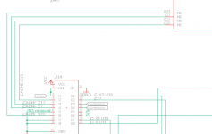
On the P33 those signals are connected to the GAL at U14:

Bildschirmfoto 2020-06-07 um 11.53.21.png

U14 is responsible to distribute the logicboard clock signal to several places on the P33.

Depending on how the sense lines are set it shifts the phase of the clock signal by routing it through it's internal registers several times as well as an external feedback loop that's not populated on the P33s that I have seen so far.

The equations inside U14 are as follows (all inputs are defined active high):

Code:
/o19 = /i2 * /i4
    + /i2 * i3 * /i7
    + /i2 * /i3 * i7
    + /i3 * /i7 * /f14
    + i3 * i7 * /f14
o19.oe = vcc
/o18 = /i4
o18.oe = vcc
/f17 = i2
f17.oe = vcc
/f16 = f17
f16.oe = vcc
/f15 = f16
f15.oe = vcc
/f14 = /i3 * /f15 * /i7
    + i3 * f16 * i7
f14.oe = vcc
/o13 = /i2 * /i4
    + /i2 * i3 * /i7
    + /i2 * /i3 * i7
    + /i3 * /i7 * /f14
    + i3 * i7 * /f14
o13.oe = vcc
/o12 = i2 * /i4
    + i2 * i3 * /i7
    + i2 * /i3 * i7
    + /i3 * /i7 * f14
    + i3 * i7 * f14
o12.oe = vcc


What it also does is just passing through the state of the C17 signal to somewhere else. This goes to the GAL at U12.

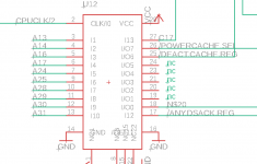
U12 implements part of the address decoder and some state machine I did not fully understand yet.

Bildschirmfoto 2020-06-07 um 12.10.06.png

Code:
CLK=1 i2=2 i3=3 i4=4 i5=5 i6=6 i7=7 i8=8 i9=9 i10=10 i11=11 GND=12 
/OE=13 i14=14 o15=15 f16=16 rf17=17 rf18=18 rf19=19 rf20=20 f21=21 
o22=22 i23=23 VCC=24 

@ues 0000000000000000
@ptd unused

equations

/o22 = /i6 * i7 * i8 * /i9 * i10 * /i11
o22.oe = vcc
/f21 = gnd
f21.oe = gnd
rf20 := /rf19 * /rf18 * rf17 * /f16 * /i14
    + rf19 * rf18 * rf17 * /f16 * /i14
    + /rf19 * rf18 * /rf17 * /f16 * /i14
    + rf19 * /rf18 * /rf17 * /f16 * /i14
rf20.oe = OE
rf19 := i14
    + f16
    + rf20 * /rf18 * rf17
    + rf20 * rf18 * /rf17
    + /rf20 * rf19
rf19.oe = OE
rf18 := f16
    + i14
    + /rf20 * rf19 * rf17
    + rf20 * rf18
    + /rf19 * rf18
rf18.oe = OE
rf17 := f16
    + i14
    + rf20 * rf17
    + rf19 * rf17
    + /rf18 * rf17
rf17.oe = OE
/f16 = /i23 * i8 * /i9 * i10 * /i11 * /i14
    + i2 * i3 * i4 * /i5 * /i6 * /i7 * i8 * /i9 * i10 * /i11 * /i14
f16.oe = vcc
/o15 = i23 * rf20 * /f16 * /i14
    + i23 * rf19 * /f16 * /i14
    + i23 * rf18 * /f16 * /i14
    + f21 * rf20 * /f16 * /i14
    + f21 * rf19 * /f16 * /i14
    + f21 * rf18 * /f16 * /i14
    + f21 * rf17 * /f16 * /i14
o15.oe = vcc


As you can see it is decoding the select signal for the P33s registers on o22 - it becomes active whenever the address lines match $52xx xxxx.

Down below the feedback/output f16 decodes for other I/O accesses that take place (notice how the logicboard I/O space is mapped in the $50xx xxxx range)

It becomes active when either of those two conditions is met:

-the address lines match $5xxx xxxx (I/O range) and there's an active data strobe acknowledge as well as C17 is low

-the address lines match $5001 6xxx (SWIM) and there's an active data strobe acknowledge

The first condition will become true if the jumper on C17 is set but it will only be the second condition that gets triggered with the C17 jumper removed.

What does that tell us? No idea... why is it a problem on one P33 while it isn't on another? Wish I'd know.

Pictures of both of your P33s would help to see speed markings and Daystar part number stamps on the GALs to make out if they are the same as mine or some other revision.


apm

Well-known member
All very interesting, thanks. I've tried removing jumpers C17 and B23. Now the floppy drive works with the bad P33 (hooray), and there is a modest improvement in the Radius card. Occasionally it will flicker the default grey screen with Radius logo briefly on startup, and more occasionally it will keep working as the system loads. Sometimes it still doesn't work.

However, the other issues haven't changed. Accessing address $5207 0000 still results in a hang (every other address of the form $520x 0000 works fine). And the same issue persists with random errors (illegal instruction, bus error, etc.) popping up when the card has heated up for a long time. This appears to be bits randomly flipped on instructions loaded from memory, based on what ends up in the registers compared to what is displayed when I disassemble the most recent code in MacsBug.

Curiously, when the card heats up, the Radius card becomes more likely to work.

A finger temperature test (carefully, given the CRT) reveals that the 68030 gets rather warm, and it appears that U13 is also pretty warm, and maybe U11 and U9 as well.

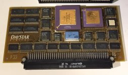
Here's the good P33 belonging to James:

P33_good.jpg

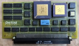
And here's the bad one I have. Not sure about the source of corrosion on the CPU and FPU; maybe it was in a battery explosion machine at some point?

P33_bad.jpg

I can try the resistor modification next. To confirm, do you want me to short out C1 on the P33? What's the function of C1?


IlikeTech

Well-known member
By any chance do you have a scope?  I would test that 50 MHz clock to make sure it's stable.


Bolle

Well-known member
Interesting... those two both have the supposedly newer GAL revision. Part numbers on mine are all starting with 25-0016* while yours both are 25-0017*

I wonder if there are any actual differences in the code. It seems the new revisions come along with faster chips being used for U16, U17 and U18.

The GALs are getting pretty hot depending on what they have to do, that's normal. I would still try to maybe swap the CPU and FPU between both of your cards and see what happens just to be sure.

To confirm, do you want me to short out C1 on the P33? What's the function of C1?
Yes. C1 has GND on one end and the clock signal that just went through the resistor right next to it.

Not sure what value should go there but terminating a clock signal with just two resistors is a valid thing to do as well.

I got it like that on both of my original PowerCaches as well as my clone prototypes (and it's done the same way on the DiiMO btw) so it's safe to do.

btw: any chance you and James would lend me those two cards to read the GALs and see what's inside them compared to the dumps I got.

(which I'll publish sometime soon after cleaning up the schematics - don't want to be greedy or hoard any of the knowledge for myself or anything ;) )

Unfortunately I'd need both cards because there is a single PALCE chip on either one which can't be read out easily.

 
Last edited by a moderator:

Bolle

Well-known member
Is the extra jumper wire to ground installed on James adapter on the /CENABLE pin so the cache actually gets enabled?

Otherwise that would explain why it looks like your card seems to be working in his adapter.

Another thing to try is to pull up the /CFLUSH signal at the cache slot connector of your P33 or the adapter using a 1-5k resistor.

It‘s at pin C5 and has VCC pins on either side right next to it so you can conveniently put a small SMD resistor between.

That signal is not connected on the adapter and is floating on the P33. It only connects to an input on U10. Lattice GALs have internal pullups that work really well so no external pullups needed. Your card has a PALCE chip at U10 which some of them should have internal pullups as well depending on the exact chip type.

With the Atmel replacement I used on my clone protos which don’t have internal pullups the exact same thing would happen - crash when the cache is active or the control panel is launched. An external pullup fixed that.

 
Last edited by a moderator:

apm

Well-known member
Thanks, I'll try that. I do have a scope so I can probe any signals you think would be relevant. I could look at the 50MHz clock but I'm not sure I'd get much out of that: my scope only has 70MHz BW, and I'm not confident the waveform wouldn't be affected by the capacitance of the probe.

However I might go sleuthing for a pin that toggles on the access to $5207 0000. Which GAL is responding to the specific accesses to $5205 0000, $5206 0000 and $520F000?

I'd be happy to send you my P33 for inspection and disassembly. I think James's one is in regular service though, so I don't know if just the one is useful.


apm

Well-known member
Progress: adding the pull-up to /CFLUSH has fixed the crash-on-cache issue. I can now boot with cache enabled and open the control panel. I can also display address $5207 0000 now.

However the other issues remain unresolved: the card still goes unstable and crashes after it heats up for a while, and the Radius card still works intermittently, if at all.

I'll try the clock modification next. Happy to send the card to you for testing and documentation, or let me know if you have other suggestions.


kiag

Member
Can I add a couple questions? I have 2 of the non-universal Powercache 50 MHz cards which behave similarly. The cards are slightly different, one labeled 1990 and one 1991, with slightly different chip layouts. One of them crashes instantly when cache is enabled, one crashes as soon as something is done (a window closed for instance). 
 

I just want to confirm: you are describing soldering a 5k ohm resistor from the C5 pin to either C4 or C6? I am fairly non-handy with a soldering iron but I’m pretty sure I can manage that. If I did that on the adapter would that interfere with other accelerators working? I’m currently using a Carrera 040. 
 

Also, a weird question but, is this a failure of some sort on the cards or are they working as designed? I am thinking about selling one or both but don’t know if I could list them as “tested working” in good conscience. I’ve looked at buying a cheap IIci to test them in, but apparently “cheap” and IIci are words that don’t go together well. Thanks. 


apm

Well-known member
Finally got a chance to add the resistors to R24 and R26 and the bridge across C1. There seems to be some improvement: the card no longer goes unstable after it heats up, provided there's no Radius card installed.

However, the Radius Color Pivot card still doesn't work, and if the Radius card is installed, the accelerator goes unstable when it heats up, like before. I can run the Mac for a long time with no Radius card with no problems, then attach the Radius card (P33 still warm) and the stability problems immediately resurface. So it is the P33 heating up that makes the difference.

Does the signal at R24 and R26 come out to the cache slot connector anywhere? I'm wondering if this might be a signal quality problem from having too many long traces on a high-speed signal.


apm

Well-known member
Update: I think the problem has something to do with the CPUCLK signal (i.e. the 16MHz one from the logic board), not the 50MHz clock. Specifically, I suspect the problem is clock skew from the propagation delay on the 74ACT86 XOR gate on the adapter.

When I take this IC out of circuit and bypass both relevant signals (to the P33; to the passthrough) with 10 ohm resistors, the P33 seems to remain stable with the Radius card plugged in. The Radius card doesn't seem to be working at the moment, even by itself, so that needs more investigation.

Looking at some datasheets, I wonder whether a 74F86 might perform better than a 74ACT86; the former has a tighter guarantee on propagation delay across temperature.


Bolle

Well-known member
That's really interesting. I didn't experience something like that yet with any of the PowerCache I have.

On the original Daystar SE/30 adapter the CPUCLK signal is passed right through.

On the DiiMO/Artmix adapter that signal is buffered in the GAL and split up for the passthrough and accelerator slot so each gets their own buffered copy of the CPUCLK signal.

When adding a PDS card and an accelerator without buffering the CPUCLK line you can overload it and the video logic on the logicboard will start to fail with too much load on the 16MHz clock... that's why adding some kind of buffering for the clock signal is kind of necessary as soon as multiple PDS cards are added.

On my adapter the buffering takes place in the 74*86 and it is sending out two separate signals to the passthrough PDS and the accelerator slot just like the DiiMO/Artmix adapter.

It also opens up the possibility to flip the clock signal 180° which is needed to get the Turbo040 and Carrera040 to play nice.

To be honest I didn't pay too much attention to what kind of 74*86 went onto the adapters. I have 74F86 as well as 74ACT86 in my parts box. Just checked through the adapters in my machines and I have both types installed, as said I didn't experience the problems you're having yet on any of them.

Might be you're hitting some kind of edge case there...

If you want to start playing you can install a GAL16V8 there as well. Clock input is on pin 1, outputs are on pins 12 (accelerator) and 13 (PDS passthrough).

Pins 2 and 5 can be used as sense pins connected to the jumpers to turn on 180° phase shifts (or whatever you want to do with the clock signal inside the GAL)

 
Top