David Cook
Well-known member
Like most of you, I use a solid-state memory card to replace dead SCSI drives. When repairing or testing old Macs, I usually place the MacSD, ZuluSCSI, or SCSI2SD drive externally. Often, these old computers do not come with a working internal drive. Depending on the Mac model, I sometimes need to install an internal SCSI terminator (or a dead drive with onboard SCSI termination) to get the external solid-state drive to work.
When I'm lucky enough to receive a computer with a working drive, one of the first things I do is to backup the old drive. But, when trying to backup old working SCSI drives to an external solid state card, sometimes the drives are incompatible. I try a combination of changing the solid-state termination options, changing the internal drive termination, or using an external terminator. In some cases, even that doesn't work. In that case, I resort to using just an external old hard drive to perform the backup, and then copy that over to solid state on a different machine.
TERMINATION
Let's talk for a moment about SCSI termination. Have you ever been on a phone call with an echo? It's really difficult to have a conversation. Right? Sometimes you mishear and sometimes you need to repeat yourself. Sometimes it is so bad you can't have a conversation at all.
Think of the SCSI cabling as the size of a room. The longer the cable, the bigger the room, the bigger the echo. The far ends of the SCSI cable are like the far walls of the room. If you put some padding there, you can eliminate most of the echo and have an easier conversation. That's what SCSI terminators do. They absorb the reflected "sound" of the SCSI conversation. Now, you don't want to deaden the conversation in the middle of the room -- only on the ends that are generating echo. You also don't want to have a dangling internal cable or external cable without anything on it. That's like appending an empty hallway, which increases echo.
To continue this analogy, adding drives to each end of the may chain help, because they are absorbing some of the sound by connecting circuitry to the cables. But, unless those drives have built-in termination (most internal hard drives do), then there is still going to be a lot of echo at the ends of those wires, because the drive circuitry is designed to sip the conversation, not deaden it.
Sometimes you get lucky even without terminators, because SCSI has parity, checksums, timeouts, and other error detection mechanisms that can ignore some of the garbage generated by echo interference and the echos themselves. But, you won't get maximum speed because each retry takes time.
Now you understand that terminators are simply wall padding that absorbs echo. And, you understand that echo is generated at the ends of the wires in the SCSI chain. Shorter wires and terminators = less echo = easier conversation = working and faster SCSI.
PASSIVE TERMINATORS
Passive SCSI terminators are just pairs of resistors going to +5V and GND. Instead of being reflected (echoed) by the end of the wire, the leftover signal energy is literally consumed in the resistors as the electrical signal proceeds to either the +5V path or the GND path through the resistors. There is one pair of resistors for each signal/data/command pin on SCSI on a passive terminator. This works well in most circumstances.
There are two downsides with passive terminators.
1. For each terminated pin (18 in total), power continually flows from +5V through a 220 ohm resistor and then through a 330 ohm resistor to ground. It is consuming this power constantly (220+550ohms across 18 parallel pins = 30.55 ohms. 5V/30.55 ohms=0.163 A * 5V * 2 terminators = 1.63 watts). So, the old power supply is working a little harder and heating up your Mac a little bit more.
2. Most Macs have a 1N4001 diode or similar (to eliminate backflow) and a 1 amp fuse (to prevent short-circuit damage). Between these components and the cabling itself, the 5V terminator power is actually less. For example, the diode probably knocks off 0.8 volts with a passive terminator on each end of the SCSI chain. The fuse and cabling eats a little bit more. Oh, and the power supply is not exactly 5 V anyway. Here's the problem: all passive terminators are the same, but individual computer SCSI setups differ. That means the off-the-shelf terminators were designed to work best in the "most likely" setups.
ACTIVE
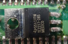
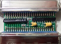
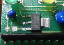
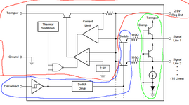
An active SCSI terminator includes a chip and/or other circuitry, not just resistors. That means it can be "smarter". The simplest design is just a 2.85V regulator connected to the positive resistors. This eliminates the variance of voltage drop caused by cables, diodes, etc, and moves some of the heat outside the Mac. But, even better designs have chips that monitor the SCSI pins and adjust voltage as needed. They can also include features such as enable/disable. Active terminators use as little as 1/100th the power when idle.
Depending on the active terminator's technology, it can make certain setups work correctly and perform faster (fewer retries). But, it isn't all-powerful magic. A failing hard drive controller board, bad cable, or other misbehaving device will still interfere with the SCSI chain. The active terminator is simply better and more energy efficient at removing echo and noise. The active terminator is not a SCSI controller or referee.
MULTIMETER TESTING
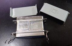
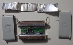
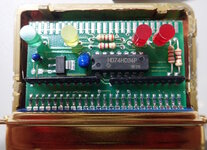
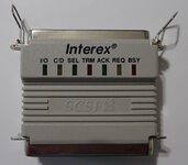
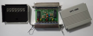
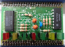
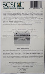
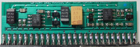
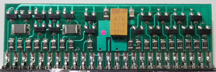
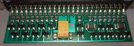
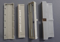
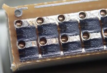
Unfortunately, since SCSI terminators are opaque, you have no way of seeing what technology is used inside. It is possible that a terminator labeled "active" is actually a fraud. I have a small collection of classic SCSI terminators. I wanted to learn how to detect which are active and which are passive.
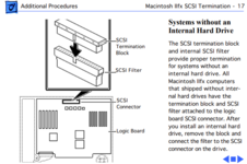
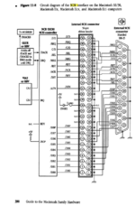
Let's begin with a figure from Apple's hardware guide. Notice the 1N4001 diode and 1 amp fuse in the middle of the diagram? That's backflow and short circuit protection. If an external device shorts or sends +12V on the terminator power pin, it isn't going to fry your Mac.
For the purpose of these tests, we're going to use Apple's internal connector numbering. This differs from the numbering normally found on Centronics 50-pin SCSI connectors. But, I want the instructions to be consistent. We are looking at the male ends of the connectors.
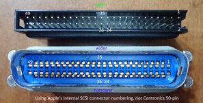
Set your multimeter to resistance mode. Put the ground probe on pin 1 for all of the tests. This is a SCSI GND pin. Touch the other probe to each of the following pins:
Pin 49: Should read almost zero ohms because this is also GND. If not, your probes aren't making good contact or you've got your terminator upside down. Notice the notch on the internal terminator and the wider side of the external terminator.
Pin 2: Should read around 143 ohms or such. This is a data pin. According the lore, there should be a 330 ohm resistor connecting this to ground. But, since all of the other resistors all connect to ground and up to +5V and back down to this pin, you've got a much more complicated path than I care to calculate. The point is, around 143 ohms means you have a standard passive terminator.
If you get a significantly different reading, you have some form of an active terminator.
Pin 26. Should read around 30.55 ohms for a standard passive terminator. A high reading indicates an active terminator. A reading that slowly climbs higher is an active terminator that includes a capacitor in the circuit. A very low (near 0) resistance says you are on the wrong pin. In any case, pin 26 is the terminator power pin. In an active terminator, this powers the chip -- rather than simply going through a resistor to each signal pin. So, a high or disconnected resistance says there is a chip in the way.
Pin 25: Bonus time. Should be really high resistance (or OL on many meters) because this pin should be disconnected. It was on all of my terminators. Surprisingly, early Macs (not terminators) ground this pin on the motherboard.
Pin 24: Bonus time. Can be really high resistance (or OL on many meters) because this pin may be disconnected, or really low resistance (near 0) because it may be grounded. It varied depending the terminator I tested. On Mac motherboards, this also may be grounded or disconnected. Weird, huh? There are other SCSI pins that were repurposed ("reserved") as SCSI evolved.
Really, if you just test pin 26 versus ground, you can determine if the terminator is active or passive. For example, I determined that:
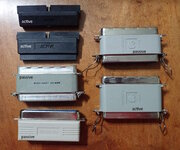
1. The internal terminators (black in image below) that I bought on eBay, are indeed active.
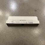
2. The smaller Apple terminator (gray, top right in the image below) is passive. That's part number 590-0695-A.
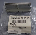
3. The longer Apple terminator (gray, bottom right) is active. That's part number 590-0772. M3503LL/A
BENCH POWER SUPPLY TEST
When I connected the active Apple terminator to my bench power supply, it drew only 2 mA (0.005 W). The passive Apple terminator drew 161 mA (0.805 W), as predicted.
The black internal terminators drew 9 mA (0.045 W) and 10 mA (0.050 W). Not surprisingly, the black terminators likely use a different technology than Apple. However, I can't determine from these readings if the two internal terminators are different from each other. Their multimeter resistance readings are very different -- but both use capacitors so I can't be sure of the significance of the resistance values.
I hope this information is useful.
- David
When I'm lucky enough to receive a computer with a working drive, one of the first things I do is to backup the old drive. But, when trying to backup old working SCSI drives to an external solid state card, sometimes the drives are incompatible. I try a combination of changing the solid-state termination options, changing the internal drive termination, or using an external terminator. In some cases, even that doesn't work. In that case, I resort to using just an external old hard drive to perform the backup, and then copy that over to solid state on a different machine.
TERMINATION
Let's talk for a moment about SCSI termination. Have you ever been on a phone call with an echo? It's really difficult to have a conversation. Right? Sometimes you mishear and sometimes you need to repeat yourself. Sometimes it is so bad you can't have a conversation at all.
Think of the SCSI cabling as the size of a room. The longer the cable, the bigger the room, the bigger the echo. The far ends of the SCSI cable are like the far walls of the room. If you put some padding there, you can eliminate most of the echo and have an easier conversation. That's what SCSI terminators do. They absorb the reflected "sound" of the SCSI conversation. Now, you don't want to deaden the conversation in the middle of the room -- only on the ends that are generating echo. You also don't want to have a dangling internal cable or external cable without anything on it. That's like appending an empty hallway, which increases echo.
To continue this analogy, adding drives to each end of the may chain help, because they are absorbing some of the sound by connecting circuitry to the cables. But, unless those drives have built-in termination (most internal hard drives do), then there is still going to be a lot of echo at the ends of those wires, because the drive circuitry is designed to sip the conversation, not deaden it.
Sometimes you get lucky even without terminators, because SCSI has parity, checksums, timeouts, and other error detection mechanisms that can ignore some of the garbage generated by echo interference and the echos themselves. But, you won't get maximum speed because each retry takes time.
Now you understand that terminators are simply wall padding that absorbs echo. And, you understand that echo is generated at the ends of the wires in the SCSI chain. Shorter wires and terminators = less echo = easier conversation = working and faster SCSI.
PASSIVE TERMINATORS
Passive SCSI terminators are just pairs of resistors going to +5V and GND. Instead of being reflected (echoed) by the end of the wire, the leftover signal energy is literally consumed in the resistors as the electrical signal proceeds to either the +5V path or the GND path through the resistors. There is one pair of resistors for each signal/data/command pin on SCSI on a passive terminator. This works well in most circumstances.
There are two downsides with passive terminators.
1. For each terminated pin (18 in total), power continually flows from +5V through a 220 ohm resistor and then through a 330 ohm resistor to ground. It is consuming this power constantly (220+550ohms across 18 parallel pins = 30.55 ohms. 5V/30.55 ohms=0.163 A * 5V * 2 terminators = 1.63 watts). So, the old power supply is working a little harder and heating up your Mac a little bit more.
2. Most Macs have a 1N4001 diode or similar (to eliminate backflow) and a 1 amp fuse (to prevent short-circuit damage). Between these components and the cabling itself, the 5V terminator power is actually less. For example, the diode probably knocks off 0.8 volts with a passive terminator on each end of the SCSI chain. The fuse and cabling eats a little bit more. Oh, and the power supply is not exactly 5 V anyway. Here's the problem: all passive terminators are the same, but individual computer SCSI setups differ. That means the off-the-shelf terminators were designed to work best in the "most likely" setups.
ACTIVE
An active SCSI terminator includes a chip and/or other circuitry, not just resistors. That means it can be "smarter". The simplest design is just a 2.85V regulator connected to the positive resistors. This eliminates the variance of voltage drop caused by cables, diodes, etc, and moves some of the heat outside the Mac. But, even better designs have chips that monitor the SCSI pins and adjust voltage as needed. They can also include features such as enable/disable. Active terminators use as little as 1/100th the power when idle.
Depending on the active terminator's technology, it can make certain setups work correctly and perform faster (fewer retries). But, it isn't all-powerful magic. A failing hard drive controller board, bad cable, or other misbehaving device will still interfere with the SCSI chain. The active terminator is simply better and more energy efficient at removing echo and noise. The active terminator is not a SCSI controller or referee.
MULTIMETER TESTING
Unfortunately, since SCSI terminators are opaque, you have no way of seeing what technology is used inside. It is possible that a terminator labeled "active" is actually a fraud. I have a small collection of classic SCSI terminators. I wanted to learn how to detect which are active and which are passive.
Let's begin with a figure from Apple's hardware guide. Notice the 1N4001 diode and 1 amp fuse in the middle of the diagram? That's backflow and short circuit protection. If an external device shorts or sends +12V on the terminator power pin, it isn't going to fry your Mac.

For the purpose of these tests, we're going to use Apple's internal connector numbering. This differs from the numbering normally found on Centronics 50-pin SCSI connectors. But, I want the instructions to be consistent. We are looking at the male ends of the connectors.

Set your multimeter to resistance mode. Put the ground probe on pin 1 for all of the tests. This is a SCSI GND pin. Touch the other probe to each of the following pins:
Pin 49: Should read almost zero ohms because this is also GND. If not, your probes aren't making good contact or you've got your terminator upside down. Notice the notch on the internal terminator and the wider side of the external terminator.
Pin 2: Should read around 143 ohms or such. This is a data pin. According the lore, there should be a 330 ohm resistor connecting this to ground. But, since all of the other resistors all connect to ground and up to +5V and back down to this pin, you've got a much more complicated path than I care to calculate. The point is, around 143 ohms means you have a standard passive terminator.
If you get a significantly different reading, you have some form of an active terminator.
Pin 26. Should read around 30.55 ohms for a standard passive terminator. A high reading indicates an active terminator. A reading that slowly climbs higher is an active terminator that includes a capacitor in the circuit. A very low (near 0) resistance says you are on the wrong pin. In any case, pin 26 is the terminator power pin. In an active terminator, this powers the chip -- rather than simply going through a resistor to each signal pin. So, a high or disconnected resistance says there is a chip in the way.
Pin 25: Bonus time. Should be really high resistance (or OL on many meters) because this pin should be disconnected. It was on all of my terminators. Surprisingly, early Macs (not terminators) ground this pin on the motherboard.
Pin 24: Bonus time. Can be really high resistance (or OL on many meters) because this pin may be disconnected, or really low resistance (near 0) because it may be grounded. It varied depending the terminator I tested. On Mac motherboards, this also may be grounded or disconnected. Weird, huh? There are other SCSI pins that were repurposed ("reserved") as SCSI evolved.
Really, if you just test pin 26 versus ground, you can determine if the terminator is active or passive. For example, I determined that:
1. The internal terminators (black in image below) that I bought on eBay, are indeed active.
2. The smaller Apple terminator (gray, top right in the image below) is passive. That's part number 590-0695-A.
3. The longer Apple terminator (gray, bottom right) is active. That's part number 590-0772. M3503LL/A

BENCH POWER SUPPLY TEST
When I connected the active Apple terminator to my bench power supply, it drew only 2 mA (0.005 W). The passive Apple terminator drew 161 mA (0.805 W), as predicted.
The black internal terminators drew 9 mA (0.045 W) and 10 mA (0.050 W). Not surprisingly, the black terminators likely use a different technology than Apple. However, I can't determine from these readings if the two internal terminators are different from each other. Their multimeter resistance readings are very different -- but both use capacitors so I can't be sure of the significance of the resistance values.
I hope this information is useful.
- David


