Recap LC475 mainboard

Mustermann

Well-known member
Dear all,

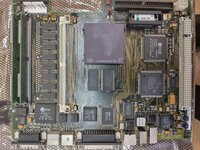
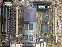
I am currently starting to recap my LC475 main board, right in time as neiter battery nor caps are leaking yet.
It is already decided that I will use ceramic capacitors.

As I am able to order them in 20x lots I am thinking about to replace all of them by 100µF 50V.
As long as they are in +5V, +12V or -5V this should be ok.

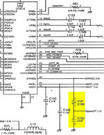
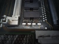
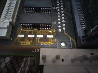
But there are two 47µF capacitors I have no clue what they are doing: C149 and C150.
They are connected in a row to "Bypass" pin of DFAC-II and ground and two testing points.

Does anyone know, what "Bypass" is doing and if these capacitors can be changed into 100µF?

Best regards,

Mustermann
 

Attachments

  • LC475 C149 C150.jpg
    LC475 C149 C150.jpg
    157 KB · Views: 36

chiptripper

Well-known member
I’d imagine they are decoupling capacitors.

You’re fine to use ceramics (or tantalums, or solid polymer etc) and you can go higher in voltage, but I would not recommend using all 100uf caps. The majority are rated at 47uf and I’d stick very close to that. There’s no reason not to, 16v 47uf caps are widely available.
 

Mustermann

Well-known member
BypassTP(14) is not connected to anything else than a testing point. Nor is Bypass(14).

So it might be that C149 is decoupling the testing point and C150 smoothes the voltage at the testing point.

If this is the only function, C149 and C150 can be 47µF or 100µF of missing at all in normal operation.

I wonder if Apple would put two big parts to each mainboard that are needed for testing only and can be placed on the other side of testing tip as well.

Other electrolytic capacitors are connected to +5V +12V or -5V.
They should not be less than designed.
So at least two of them need to be 100µF.

I can order 20 of them in a pack minimum.
That's the only reason to change the 47µ to 100µ

If I am right, increasing capacity for smoothing voltage is not bad as long as series inductance is not increasing to much.
Series inductance of ceramic capacitors is much less than that from electrolytic capacitors, so using 100µ instead of 47µ should not be an issue. (except of C149 and C150 where I do not know).
 

croissantking

Well-known member
Welcome to the forum!

Being honest here, why not just replace like for like? Why reinvent the wheel? Working this out seems to be extra effort for no gain.
 

Mustermann

Well-known member
Thank you very much for the warm welcome and the kind reply.

Replacing them one by one is not a big issue.
Just increasing the spare parts box a little.

Just interesting if someone know, what "Bypass" is doing.
 
Last edited:

Bolle

Well-known member
Does anyone know, what "Bypass" is doing and if these capacitors can be changed into 100µF?
On the older DFAC the bypass input was used to connect an external capacitor to stabilize the AC ground reference voltage that's generated internally on the chip. It's likely doing the same on the DFACII.
The datasheet specifically mentions using electrolytic capacitors here.
 

cheesestraws

Well-known member
I'm not sure where BYPASS comes from, but since this is in the audio section of the board, I'd be a bit careful about not arbitrarily replacing components with totally different components here.
 

Mustermann

Well-known member
What I found right now:

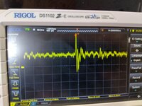
When starting up the system, BYPASS(14) pin is going down to -5V within a second an return to 0V within a few seconds.
Afterwards there are only signals of about 50mV which I assume to be cross talk (see attachment).
No difference when playing a sound.

There are Bypass capacitors in some audio amplifier designs


"The datasheet specifically mentions using electrolytic capacitors here."
As it does for all capacitors starting from 3,3µF.

I assume that was a decision of price or the fact that 47µF ceramic capacitors were not existing in 1991.

Is there any additional hints to use electrolytic capacitors for these two capacitors (C149, C150) other than the other 47µF capacitors in the schematic (electrolytic capacitors as well)?
 

Attachments

  • Bypass.jpg
    Bypass.jpg
    2.9 MB · Views: 17
Last edited:

chiptripper

Well-known member
Ceramics generally feature low ESR. In some circuits higher ESR is desirable (eg. noise reduction in DC-DC, antiresonance in decoupling).

I have used ceramics to replace LB caps without any discernible negative impact. But never 47uf 16v. Where I live, ceramic SMDs above 10uf are really expensive compared to electrolytic/tantalum/polymer. And they’re tiny. I don’t see the upside.
 

Mustermann

Well-known member
I have used ceramics to replace LB caps without any discernible negative impact. But never 47uf 16v. Where I live, ceramic SMDs above 10uf are really expensive compared to electrolytic/tantalum/polymer. And they’re tiny. I don’t see the upside.
In between 2 boards are recaped with ceramics.

Those capacitors are not as important as expected.
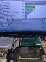
My LC475 board run at 40MHz even without ALL 47µF and 100µF (except those at the audio chip) stable.
The board run with 70µF Ceramics instead of 47µF fine as well.

I ordered 100µF 50V ceramics from China. What I got was 70µF (at least what my C-meter says).
I also ordered 47µF and 22µF 50V from China and got 33µF and 20µF.
Not really what I expected but still good for what I planed.
So I replaced the 47µF by a 70µF ceramic and the 100µF by a pair of 70µF+33µF ceramic.

For the two in the audio circuit I tried to be as accurate as possible. A pair of 33µF and 20µF is 47µF +12% so should be fine.

Ceramics were not so expensive: ~1€ per capacitor including shipping and taxes for 70µF (as they should have been 100µF I got 30% discount at the end that is not included in the 1€). Ok, significant more than Tantalum but less expensive than OS-CON capacitors.

They are not so tiny as well. 100µF 50V are offered in 2220, 1812, and 1206 size. I choose the 1812 size.

One downside I have to notice:
The metal contact of 1812 Ceramic is much broader that the contact of an Electrolytic or Tantalum.
So I was concerned that they may come in contact with the other tracks below them.

At 3 of them there is no trace below. For the rest I put a small piece of Kapton tape between the PCB and the capacitor prior soldering them in.
Worked well.

So at the end: Tantalum that are rated for a voltage much above the needed voltage might be easier and cheaper and will work as well.
Ceramics have a lower ERS as OS-CONs do, but i do not expect from both of them that they are a "Magic Sauce".
Ceramics and Tantalum are easier to distinguish from old Electrolytics than OS-CONs are. (Maybe helpfull to be sure if the board was recaped or not after 10 additional years)
 

Attachments

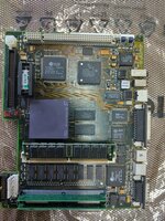
  • Electrolytics removed.jpg
    Electrolytics removed.jpg
    2.7 MB · Views: 10
  • 40MHz without Electrolytics.jpg
    40MHz without Electrolytics.jpg
    2.4 MB · Views: 10
  • Traces nearby.jpg
    Traces nearby.jpg
    396.6 KB · Views: 10
  • Kapton protection.jpg
    Kapton protection.jpg
    345.4 KB · Views: 10
  • Soldered with a lot of Flux.jpg
    Soldered with a lot of Flux.jpg
    4.7 MB · Views: 13
  • Cleaned with IPA.jpg
    Cleaned with IPA.jpg
    3 MB · Views: 15
Last edited:

chiptripper

Well-known member
Interesting, good to know there’s some wiggle room with capacitance. Thanks for the update.

This year I’ve switched almost entirely to solid polymer caps. They’re a perfect match for footprint / contact placement, and they are much less expensive than tantalum or OS-CON. They do seem to be low-ESR compared to electrolytics, but this hasn’t caused any issues for me.
 

zigzagjoe

Well-known member
I would be extremely leery of those MLCC capacitors you're using. Most likely you've purchased some caps rated for a tenth of that voltage and likely lower capacitance too.

If you search a reputable source - digikey, mouser, etc - you'll note that you simply can't find 50v and 100uf in that package or anything similar in size. Generally they will top out at 10v, even at lower capacitance rating. So: 50v 100uf in 1812 is not physically possible as it'd have to be much larger.

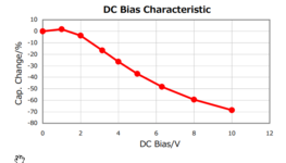
Moreover, if we assume they're actually 10v caps that are misadvertised (6.3v is more likely), keep in mind MLCC caps derate badly with voltage. Here's the graph for one of those 100uf 10v caps:

1732395084843.png

As you've noted the boards mostly work without any of the bulk capacitance (the electrolytics), so it's not technically critical, but you're likely operating with a fraction of the capacitance you think you have. Use electrolytic, polymer, or tantulums; this isn't a good application for MLCC caps.
 

Attachments

  • c4532x5r1a107m280kc.pdf
    132.4 KB · Views: 3

Mustermann

Well-known member
At least they do not blow up or short circuit or change capacitance at 46V within half an hour (That is was what I tested with my lab power supply).
I assume they are not 50V but I would be fine with half of that as well.
I know about DC de-rating but this is depending on the max Voltage.

Unfortunately my C meter is not able to measure this.
Will two capacitors in a row, charged with +10 V and -10V so overall Voltage is 0 V be an opportunity to measure this with a standard C meter?
 

zigzagjoe

Well-known member
At least they do not blow up or short circuit or change capacitance at 46V within half an hour (That is was what I tested with my lab power supply).
I assume they are not 50V but I would be fine with half of that as well.
I know about DC de-rating but this is depending on the max Voltage.

Unfortunately my C meter is not able to measure this.
Will two capacitors in a row, charged with +10 V and -10V so overall Voltage is 0 V be an opportunity to measure this with a standard C meter?

Optimistically these are 10v rated parts and more likely 6.3v or below. Those are at least possible in that form-factor. Anything more is wishful thinking, I'm afraid.

You would probably have to construct a R-C circuit with the bias, then feed pulses in & measure w/ a scope to get an idea of the actual capacitance. It would be a pain since you will also have to validate your testing methodology. Personally, I'd not use parts of dubious provenance that are already provably wrong on at least one specification with no way to reliably validate the other key specifications.

It's really not a corner worth cutting IMO.
 

Mustermann

Well-known member
I did some tests:
- My meter is not able to measure a charged capacitor. Always discharge while measuring.
- If I put 2 capacitors in a row, I can charge them with opposite voltages so the overall voltage is 0V and the capacitance is halved.
- Starting with the 22µF 50V ceramic I ordered from China I got this results
0V->11µF->100%
5V->9,3µF->85%
12V->6,9µF->63%
30V->2,97µF->27%
35V->2,8µF->25%
Based on the graphic zigzagjoe shared, there should be 32% at nominal voltage, so I assume those are 22µF 25V.

- Next 35µF and 70µF in a row (as there is only one of each value left)
0V->27,6µF->100%
5V->11,5µF->42%
12V->4,7µF->17%
30V->1,9µF->7%

Zigzagjoe is right: They behave as 70/35µF 6,3V

It seems I went into a China fake product trap.

Real 100µF 50V would have 100µF at 5V and 90µF at 12V
Those I bought are assumed to have 30µF at 5V and 12µF at 12V.

That is not what I planned.

The best Mouser has are:
47µF 16V as 2220. This would give 40µF at 5V and 28µF at 12V.
47µF 25V as 2220. This would give 45µF at 5V and 30µF at 12V but they are >4€ each.
Based on that I will no longer try to use Ceramics.

Next I will try Polymer capacitors. OS-CON is the Panasonic brand for them. But ChemiCON does offer them as well.
 
Last edited:

Mustermann

Well-known member
Not to hijack the topic, but I am about to order these for a total of 5x 475 board recap; might be interesting


I am switching over from yellow tantalums to black polymer tantalum after one of my Bolle SE/30 boards catched fire
You do not hijack, as it seems this more about capacitors in general than Ceramics only now.

I do not have any clue about Polymer Tantalum but I noticed both of them are 7,3mm in lenght instead of 6,3mm the original capacitors were.
Might work but is a little tight.
 

chiptripper

Well-known member
Moreover, if we assume they're actually 10v caps that are misadvertised (6.3v is more likely), keep in mind MLCC caps derate badly with voltage. Here's the graph for one of those 100uf 10v caps:
Thanks for this info on MLCC derating! I have historically used a sprinkling of MLCCs (10uf 16v and 1uf 50v) because they’re easy to install, non-polar, inexpensive, and haven’t caused problems. But “hasn’t caused me any problems so far” is a trap, IMO, so I think I’ll stop using them.
 

Mustermann

Well-known member
If using MLCC that are 5x - 10x in voltage, DC derating should not be an issue.
1uF 50V in 5V environment should be fine (if not faked).
 

zigzagjoe

Well-known member
Yeah, MLCC are fine as long as you have authentic parts and significantly overrate the voltage if you're using them in an application which will see a high DC bias.

I'd steer clear of chinese caps always and only order what you can get via a parts house like digikey or mouser since there's no easy way to validate parts are what they should be.

@Mustermann That's unfortunate news, if unsurprising, but interesting testing methodology. I'm having a little bit of difficulty understanding how you're introducing the DC bias to test with though. Would like to hear more!
 
Top