Hi guys,
I recently picked up 2 q700. Both do not have boot chime or video. Upon closer inspection I see some modifications.
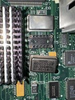
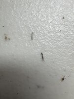
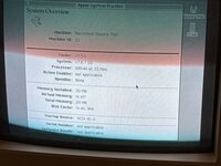
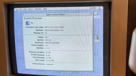
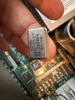
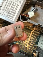
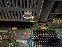
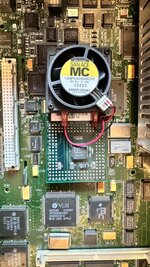
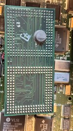
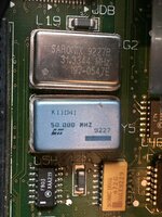
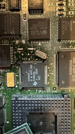
On 1st the oscillator was removed and there is plastic on top of it (pic 1). Does the oscillator (pic 2,3) with bent pin go in there? There is oscillator tied to PSU (pic 4). I am guess that is the stock one.
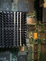
On 2nd CPU was upgraded. When I pulled the board I noticed that metal part was loose (pic8). Also upon closer inspection I see two pins missing on bottom left corner (pic 6)
First 4 pictures are from 1st q700 and last 4 are from 2nd one.
I recently picked up 2 q700. Both do not have boot chime or video. Upon closer inspection I see some modifications.
On 1st the oscillator was removed and there is plastic on top of it (pic 1). Does the oscillator (pic 2,3) with bent pin go in there? There is oscillator tied to PSU (pic 4). I am guess that is the stock one.
On 2nd CPU was upgraded. When I pulled the board I noticed that metal part was loose (pic8). Also upon closer inspection I see two pins missing on bottom left corner (pic 6)
First 4 pictures are from 1st q700 and last 4 are from 2nd one.
 shouldn't be too difficult though