KeroXiee74
Member
Hi folks,
It was last week. An idiotic shipping company has destroyed my LC575.
I bought this at an auction in Japan, but I abandoned it because the main body will be collected if it is guaranteed by the shipping company.
I made a project to change my mind and help the Color Classic owner who is having trouble with analog failure :lol:
And I wanted to enjoy this experiment...The final goal of this project is to display 640X480 VGA.
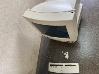
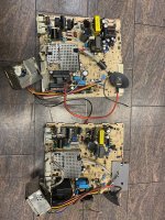
By the way, I verified the difference between the LC575 and Color Classic analogs:
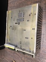
1, Difference in size. The depth is the same and the slots and back panel are exactly the same.
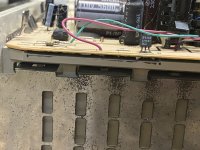
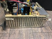
*The image below is after cutting.
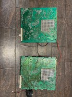
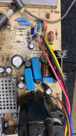
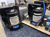
2, ZP1 transformer wiring. The LC575 is close to wiring to run VGA mode if it is Mystic.
3, Stereo Audio output.This is not implemented in color classic only, the pattern is on the board. Two power ICs are mounted and it has a stereo output.
Did not discover any other differences...
The actual works
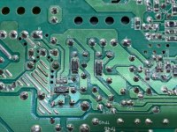
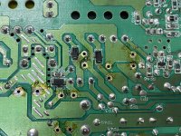
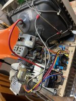
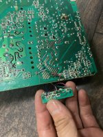
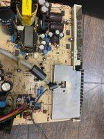
Cut the extra part. On the left side when viewed from the back, there are some surface mount resistors centered on the POT, and the cut line crosses them.
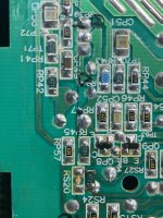
Just shift the two resistors that are on the cut line upwards, and attach a total of 6 jumper wires after cutting the others so that there is no problem in terms of functionality.
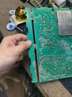
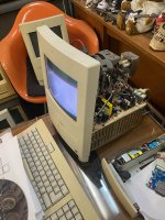
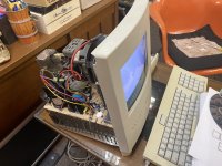
The chassis is cut according to the top on which the board slides. The size of the image fits perfectly in the case. Left and right 1.53 inches (38 mm) are cut.
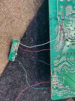
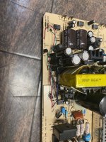
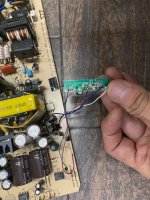
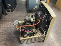
Power-on and startup
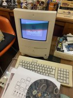
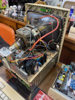
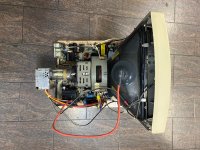
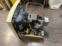
I picked up a jumper miss with a carefully cut pattern. I imagined a failure or destruction, but I connected a 10 inch Color Classic CRT and turned on the power.
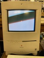
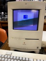
It started successfully, but the display area became smaller. It’s about 60%...lol 8-o
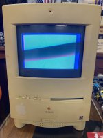
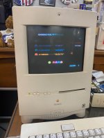
After that, I also confirmed that it was connected to a 13-inch CRT of LC575 and output at 100%. This is of course a natural result, but I wanted to see the difference between the ribbon cable that connects analog and logic. There is also a display license line.
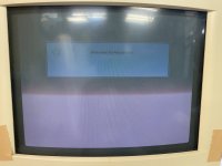
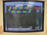
I have a book of DoopingMac written By Tak Imai, Who created Mystic and Takky. There is a "10 inch Trinitron CRT designed as an Apple genuine 12 inch CRT compatible single resolution monitor. The horizontal sync frequency is 24.45 kHz and the vertical sync frequency is 60.15 Hz. The horizontal sync frequency is 35.0 in 13 inch mode. kHz, the vertical sync frequency will be 66.67 Hz."
I decided to think a little until I had a perfect idea...Please help if anyone understands the perfect concept of this analog board. And I hope this project can save as many Color Classics as possible from this world ;D
It was last week. An idiotic shipping company has destroyed my LC575.
I bought this at an auction in Japan, but I abandoned it because the main body will be collected if it is guaranteed by the shipping company.
I made a project to change my mind and help the Color Classic owner who is having trouble with analog failure :lol:
And I wanted to enjoy this experiment...The final goal of this project is to display 640X480 VGA.

By the way, I verified the difference between the LC575 and Color Classic analogs:
1, Difference in size. The depth is the same and the slots and back panel are exactly the same.
*The image below is after cutting.

2, ZP1 transformer wiring. The LC575 is close to wiring to run VGA mode if it is Mystic.
3, Stereo Audio output.This is not implemented in color classic only, the pattern is on the board. Two power ICs are mounted and it has a stereo output.
Did not discover any other differences...
The actual works
Cut the extra part. On the left side when viewed from the back, there are some surface mount resistors centered on the POT, and the cut line crosses them.

Just shift the two resistors that are on the cut line upwards, and attach a total of 6 jumper wires after cutting the others so that there is no problem in terms of functionality.

The chassis is cut according to the top on which the board slides. The size of the image fits perfectly in the case. Left and right 1.53 inches (38 mm) are cut.


Power-on and startup
I picked up a jumper miss with a carefully cut pattern. I imagined a failure or destruction, but I connected a 10 inch Color Classic CRT and turned on the power.
It started successfully, but the display area became smaller. It’s about 60%...lol 8-o

After that, I also confirmed that it was connected to a 13-inch CRT of LC575 and output at 100%. This is of course a natural result, but I wanted to see the difference between the ribbon cable that connects analog and logic. There is also a display license line.


I have a book of DoopingMac written By Tak Imai, Who created Mystic and Takky. There is a "10 inch Trinitron CRT designed as an Apple genuine 12 inch CRT compatible single resolution monitor. The horizontal sync frequency is 24.45 kHz and the vertical sync frequency is 60.15 Hz. The horizontal sync frequency is 35.0 in 13 inch mode. kHz, the vertical sync frequency will be 66.67 Hz."
I decided to think a little until I had a perfect idea...Please help if anyone understands the perfect concept of this analog board. And I hope this project can save as many Color Classics as possible from this world ;D


