Powerbook RAM expansion card modifications

TrueNorthStrong

Well-known member
In the continuing saga of the 180c I'm working on, I dove right in to tackling a memory expansion modification to get it up to that sweet 14MB limit.
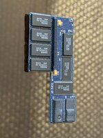
The card is a 4MB expansion card but has all the pads for 10MB.
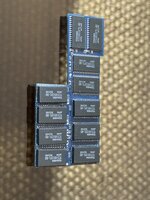
I wasn't able to source exact replacement chips, instead I found them in a standard SOP package (versus the TSOP that's on board standard).
This necessitated the legs to be folded under the chip and tacked on that way. There's a wax coating of sorts on the board edged which made soldering to those contacts rather tricky, but I believe I got it (sure ain't too pretty though).
I have not yet gotten to installing the filtering caps, but I wanted to see in this halfway state how the system would respond to it being installed. I get death chimes on boot, doesn't even manage to get to a dead mac screen to show any diagnostics.

So, I'd like to understand things at this stage so far:
- Are those caps strictly necessary for the card to function? Or, missing those, would it still manage to boot but not see the additional memory?
- Presumably the lines on each chip are commoned together or connect in some pattern to the connector. Does anyone know of a resource to refer to so I can confirm that all lines on all chips are actually connected correctly?

Any other tips about doing this work correctly would be great.

Thank you!
 

finkmac

NORTHERN TELECOM
those are almost definitely decoupling capacitors. mostly there to clean up noise and such.

your issue is either the RAM ICs you got or your solder job. make sure the pinout matches between SOP and TSOP
 

TrueNorthStrong

Well-known member
Thanks! I did not think to double check the pinouts but I really should have. It's the same IC part number aside from a differentiator (missing a "T") to indicate it's just SOP. Nevertheless I'll go dig up the sheets and compare.

As for checking the soldering job, how best would I go on about that aside from visually? My rough understanding of RAM informs me that many of the lines will just be common across them, with just a few being specific to each chip. I'm sure the pinout will be useful in this regard but if you have additional advice I'm all ears!
 

TrueNorthStrong

Well-known member
Sneaky little update. The datasheet for the FL and FTL variants of the chips I've got here are identical. The pinout section is marked as relevant for both of those. So, it's down to the chips or the soldering. I'll contact the seller to ask if they run tests on chips before they send them out or if they just have old stock kicking around.
 

TrueNorthStrong

Well-known member
i'd say break out the multimeter and start beeping out your solder job
That's the idea, but I'll need to have an idea of what to expect! The card is packed quite densely so I can't just test from leg to pad, such as it is. That's why I was wondering which pins on the chips would be common so I could at least beep those out for validation. As for the other ones...

I'd install these before troubleshooting any further.
Thanks. I've got an order to submit for various other projects so I'll go add those on. Sounds like 0.1uf is the word, eh?
I've noticed some bare spots for resistors as well. Should I be looking into populating those spots too?
 

finkmac

NORTHERN TELECOM
resistors might be for selecting capacity... see if you can find pictures of a higher capacity card.
 

TrueNorthStrong

Well-known member
That was one of my guesses, but I have not been able to find photos of a card that looks similar. There's little identification on it; only a brand and a date. Kelly Micro, 1994. It's also not the same shape as the ones I can see online so I may have to simply do a bunch of experimentation to figure this out.

If a photo of the card as it is now will help, I'll go break out the good camera and take some.
 

TrueNorthStrong

Well-known member
Here’s some quick photos of the card.

I was not aware this card is a bit non standard so I don’t have any photos of it prior to modification. Whoops.

My dubious soldering work is on full display here. The chips are a bit off kilter. I’ll be probing them out this weekend to see if any connections are bad.
 

Attachments

  • IMG_4866.jpeg
    IMG_4866.jpeg
    1.2 MB · Views: 21
  • IMG_4867.jpeg
    IMG_4867.jpeg
    1.5 MB · Views: 19

croissantking

Well-known member
Oh I’ve done loads of work on these RAM cards - I’ve maxed out about five of them, including a 180c card.

The resistors R1 and R2 are likely a pull-up and pull-down to /FASTRAM. These set a compatibility mode for older PowerBooks 140/170 and will limit the card to 6MB and add an extra wait state. On all 10MB cards I’ve seen, these are not present. So I would advise removing R2.

As you already worked out, you need to populate all the decoupling caps.

If it still death chimes then the issue will be one or more faulty chips. What I did when I had this issue (which was constantly, because these chips are easily damaged) was to remove one bank at a time (i.e. four chips on the same RAS line) until it worked again. Then I would know which set of four chips contained a faulty part, and I could test them individually. I swapped suspect chips onto small, working 2MB cards to test.
 
Last edited:

finkmac

NORTHERN TELECOM
good point about the fastram bit.. i was just reading the devnotes and shoulda remembered.

the developer note outlines that, good to keep around for reference...

with regards to suspect memory ICs, I wonder if some sort of modified card with a TSOP socket or something would be worthwhile @croissantking.
would certainly minimize heat stress on boards and RAM
 

croissantking

Well-known member
good point about the fastram bit.. i was just reading the devnotes and shoulda remembered.

the developer note outlines that, good to keep around for reference...

with regards to suspect memory ICs, I wonder if some sort of modified card with a TSOP socket or something would be worthwhile @croissantking.
would certainly minimize heat stress on boards and RAM

Yes perhaps it would be a good idea. I think the PSRAM chips in particular are really fragile and can be killed by overheating. They’re certainly far more sensitive than any of the FPM RAM chips I’ve played around with.

I used low temperature solder (like chip quik) for moving around the chips for testing, which meant that I could turn the hot air temp right down.
 

TrueNorthStrong

Well-known member
OK, sounds good! Thanks all for the tips. I did find some suspect solder joints and touched those up already. However, the majority of the issues I'm having stem from not having a hot air station. I plan to snag a cheeky lil 858D today or tomorrow to resolve that. Doing it with an iron is possible but with the tight tolerances it's not fun.

I'll have to consider the temperatures too. I'm just using my old roll of Radioshack leaded solder for the work so something specific for this task would be in order. What specific temps are you using?

Also, do you know of any resource that has the pinout for the 70 pin connector? One thing I was attempting to do last night was beep out the connections on the chips to see if I could isolate any broken connections. I was having a hard time understanding if and when certain pins on the chips are commoned together or not. I read up on an old Arstechnica post about DRAM theory and wiring, but what I garnered from that didn't seem to align with this card. For instance, the data I/O pins seem to be specific per chip. However, with 8 I/O pins per chip and 20 chips total, that alone exceeds the number of available pins on the connector. So, clearly those are commoned in some cases and in others not.

Just taking any and all opportunities to learn more. Right now my work is exceptionally slow so I have too much spare time on my hands. I like to use that productively.
 

croissantking

Well-known member
OK, sounds good! Thanks all for the tips. I did find some suspect solder joints and touched those up already. However, the majority of the issues I'm having stem from not having a hot air station. I plan to snag a cheeky lil 858D today or tomorrow to resolve that. Doing it with an iron is possible but with the tight tolerances it's not fun.

I have a hot air station, but I mostly use this to aid in removal. For fitting the new chips, I'll use plenty of flux and drag the solder along the pins, using a small tip and the iron set to 400C.

I'll have to consider the temperatures too. I'm just using my old roll of Radioshack leaded solder for the work so something specific for this task would be in order. What specific temps are you using?

With chip quik or similar, you don't even need to use hot air (although I did, a bit, just to speed things up - but it was at like 200 degrees C).

Also, do you know of any resource that has the pinout for the 70 pin connector? One thing I was attempting to do last night was beep out the connections on the chips to see if I could isolate any broken connections. I was having a hard time understanding if and when certain pins on the chips are commoned together or not. I read up on an old Arstechnica post about DRAM theory and wiring, but what I garnered from that didn't seem to align with this card. For instance, the data I/O pins seem to be specific per chip. However, with 8 I/O pins per chip and 20 chips total, that alone exceeds the number of available pins on the connector. So, clearly those are commoned in some cases and in others not.

I think address and data lines are common and then chip select/RAS are individual to each bank.

Make sure you don't have any pins shorted together - I used some wire wool in my work area and little bits of metal got everywhere. Caused havoc with my SMD work.

Just taking any and all opportunities to learn more. Right now my work is exceptionally slow so I have too much spare time on my hands. I like to use that productively.

Been there. Am there :cry: Bloody economy.
 

TrueNorthStrong

Well-known member
OK, well the hot air station will be useful then anyway since I will likely need to remove those chips for testing.
I used a magnifying glass to investigate the pins closely. No shorts that I could see. I could also beep that out to validate, I don't think any pins would be internally shorted (I'd assume then an external short would have little difference).

It'll be some time until I get in the SMD caps and get those installed. I have a tape deck with the worlds most complicated disassembly to reach an IR end-of-tape sensor that needs replacing. I've been procrastinating taking that out to identify a replacement since it's such an awful pain. But I don't want to do a digikey order for one part so I've got to get around to it now. In the meantime, is there any sense in testing the card without those caps installed? Or would it likely cause death chimes without them, and lead to a false impression on the functionality of the chips?

I only have a spare RAM daughter card around. It's working and I'd rather not mess with it but if it's somewhat compatible I may look into using that as a carrier for testing individual chips.
 

croissantking

Well-known member
OK, well the hot air station will be useful then anyway since I will likely need to remove those chips for testing.
I used a magnifying glass to investigate the pins closely. No shorts that I could see. I could also beep that out to validate, I don't think any pins would be internally shorted (I'd assume then an external short would have little difference).

It'll be some time until I get in the SMD caps and get those installed. I have a tape deck with the worlds most complicated disassembly to reach an IR end-of-tape sensor that needs replacing. I've been procrastinating taking that out to identify a replacement since it's such an awful pain. But I don't want to do a digikey order for one part so I've got to get around to it now. In the meantime, is there any sense in testing the card without those caps installed? Or would it likely cause death chimes without them, and lead to a false impression on the functionality of the chips?

I only have a spare RAM daughter card around. It's working and I'd rather not mess with it but if it's somewhat compatible I may look into using that as a carrier for testing individual chips.
Leaving them out might cause instability rather than death chimes. But YMMV (It was the case on a PB1400 homemade RAM upgrade where I left them out, and it bombed during startup).

You could get them off eBay to avoid a minimum order fee at digikey?
 

TrueNorthStrong

Well-known member
I’ve got other orders to make, I’m recapping a 20SC and a Vulcan. I just was doing the online equivalent of muttering to myself about things I ought to do.

One interesting observation I’ve made. From beeping out the pins on the existing chips I made a guide for what was common and what was not. I found that the data pins were not common. Would there be a reason why my testing would produce that, but the pinouts say they should be?
 
Top