demik
Well-known member
Hello,
I needed this to be done for a R&D project, so in case it's useful for someone else, I'm posting my notes here
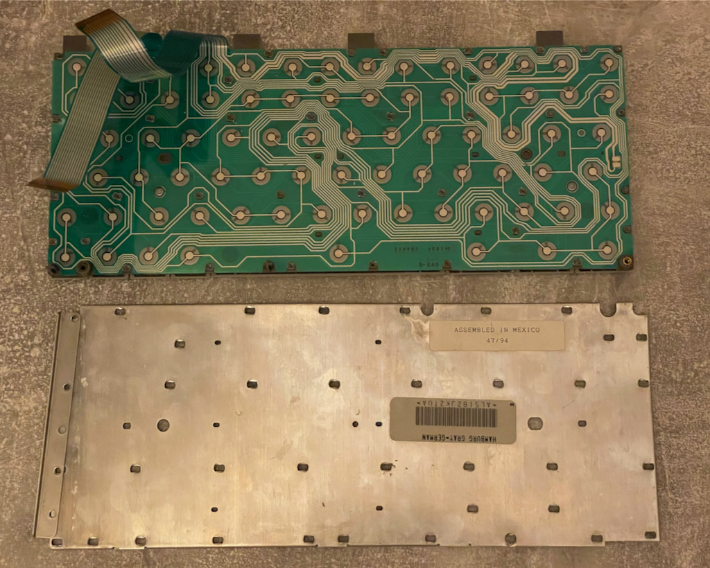
The PB5xx series have two 16 pins connector for the keyboard. They are standard 1mm pitch 16 pins ribbon connectors.
Here is a picture of the PCB below the metallic shield:
Pinout:
Observations:
- The matrix scanning is done by the PMU, most of the lines go there
- The Keyboard is NOT ADB, the PMU emulates an ADB Keyboard
- Each functions key (Power, both Shifts, Command, Option, Caps Lock, Control) has its own dedicated scanning line
- They ground their scanning line when pressed: That's how the Power button work (Ground ADB Pin 2)
- Keyboard is not NKRO
- Caps Lock LED forward voltage is 1.8V
Pin 14 and 15 connected together on J13 is for some detection. Either it's for detecting a keyboard presence, or it's for something else. Maybe detecting ISO vs US Layout ? Does someone have a PB5xx Keyboard lying around ?
I needed this to be done for a R&D project, so in case it's useful for someone else, I'm posting my notes here
The PB5xx series have two 16 pins connector for the keyboard. They are standard 1mm pitch 16 pins ribbon connectors.
Here is a picture of the PCB below the metallic shield:
Pinout:
Code:
| CON | PIN | NOTES  |
+-----+-----+--------+
| J13 | 1   | Col1
| J13 | 2   | CLED-
| J13 | 3   | CLED+
| J13 | 4   | Col2
| J13 | 5   | Col3
| J13 | 6   | Col4
| J13 | 7   | Col5
| J13 | 8   | Col6
| J13 | 9   | Col7
| J13 | 10  | Col8
| J13 | 11  | Col9
| J13 | 12  | F-GND
| J13 | 13  | Col10
| J13 | 14  | J13-15
| J13 | 15  | J13-14
| J13 | 16  | NC
+-----+-----+--------+
| J14 | 1   | NC
| J14 | 2   | ADB PU
| J14 | 3   | RSHift
| J14 | 4   | Row1
| J14 | 5   | Row2
| J14 | 6   | Row3
| J14 | 7   | Row4
| J14 | 8   | Row5
| J14 | 9   | CMD
| J14 | 10  | Option
| J14 | 11  | CapsL
| J14 | 12  | RShift
| J14 | 13  | Ctrl
| J14 | 14  | Row6
| J14 | 15  | Row7
| J14 | 16  | Row8
+-----+-----+--------+

Notes:
- J13-2 is GND on the Logic Board
- J13-15 is GND on the Logic Board
- J13-12 is GND on the Logic Board
Observations:
- The matrix scanning is done by the PMU, most of the lines go there
- The Keyboard is NOT ADB, the PMU emulates an ADB Keyboard
- Each functions key (Power, both Shifts, Command, Option, Caps Lock, Control) has its own dedicated scanning line
- They ground their scanning line when pressed: That's how the Power button work (Ground ADB Pin 2)
- Keyboard is not NKRO
- Caps Lock LED forward voltage is 1.8V
Pin 14 and 15 connected together on J13 is for some detection. Either it's for detecting a keyboard presence, or it's for something else. Maybe detecting ISO vs US Layout ? Does someone have a PB5xx Keyboard lying around ?