pizzigri
Well-known member
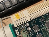
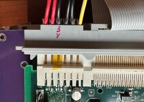
Ok, I apologize- it was not clear what were you asking. In reality, using a 630-6300 board in a 5-6400/5-6500 enclosure that also provides a 3.3v rail should not pose a problem as that pin is NC in most logic boards.(there are threads which detail this and how to make sure that indeed the pin is NC).
You can radily isolate the pins with Kapton tape for eade of mind in this case.
The thread you linked is of the problem the other way round, or how to fit a LB needing the 3.3V in an earlier enclosure that does not provide it.
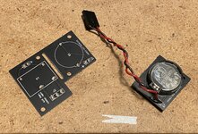
ladtl, I’m not sure what you’re asking with the coin cell mod, many of us use adapters to replace the dangerous and expensive 3.6v pram batteries with standard cr2032a ?
You can radily isolate the pins with Kapton tape for eade of mind in this case.
The thread you linked is of the problem the other way round, or how to fit a LB needing the 3.3V in an earlier enclosure that does not provide it.
ladtl, I’m not sure what you’re asking with the coin cell mod, many of us use adapters to replace the dangerous and expensive 3.6v pram batteries with standard cr2032a ?