• Updated 2023-07-12: Hello, Guest! Welcome back, and be sure to check out this follow-up post about our outage a week or so ago.

Pin slot on G3 Whisper Perch?

croissantking

Well-known member
I haven't checked. I've only seen rear case photos of the prototype, and haven't sat down with a board with the pads to check. Not sure which of my G3s has the card with the unpopulated usb footprint. I'll have to go for a rummage.
I think I have a late version of the Whisper card so I will have a look into this with a view to potentially populating/hacking it. That’s amazing that there was provision for potential USB on these.

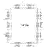
Edit: I’m only speculating but the empty chip location is 100 pin, and would appear to accommodate for example an OPTi FireLink 82c861. I bet that’s where it would go. Probably need to populate that plus some of the nearby passives to get this to work - which is why a photo of the prototype card would be useful.
 
Last edited:

NJRoadfan

Well-known member
The OPTi chip is a good guess. Look at the Rev A iMac boards, they likely have the same passives any USB equipped personality card would have used.
 

croissantking

Well-known member
Is there any other discussion online about this USB feature? I think it’s so interesting to see what could have been, since USB is an exclusive defining feature of the ‘New World’ Mac. I guess it was ready to go on later model beige G3s but marketing pulled the plug on it for some reason or other; or maybe there were reliability issues.
 

joevt

Well-known member
Beige G3 rev 3 rom Open Firmware names 5 PCI slots. First is PERCH (or perch in rev 1 and 2 rom). Next is F1 for the built-in GPU (which is scanned last in rev 1 and rev 2 rom).
Code:
   \ device-id, interrupt, presentbits \ device-id = slot-name
    0c 1c                   -1 ?probe-slot \ 0c = PERCH
    12 16                   -1 ?probe-slot \ 12 = F1
    0d 17 prsntbits      3 and ?probe-slot \ 0d = A1
    0e 18 prsntbits 2 >> 3 and ?probe-slot \ 0e = B1
    0f 19 prsntbits 4 >> 3 and ?probe-slot \ 0f = C1
 

croissantking

Well-known member
Beige G3 rev 3 rom Open Firmware names 5 PCI slots. First is PERCH (or perch in rev 1 and 2 rom). Next is F1 for the built-in GPU (which is scanned last in rev 1 and rev 2 rom).
Code:
   \ device-id, interrupt, presentbits \ device-id = slot-name
    0c 1c                   -1 ?probe-slot \ 0c = PERCH
    12 16                   -1 ?probe-slot \ 12 = F1
    0d 17 prsntbits      3 and ?probe-slot \ 0d = A1
    0e 18 prsntbits 2 >> 3 and ?probe-slot \ 0e = B1
    0f 19 prsntbits 4 >> 3 and ?probe-slot \ 0f = C1
Neat. What does PERCH stand for? Personality something?
 

croissantking

Well-known member
I've ordered a 2-port USB card off eBay to take parts off. I'll shortly start a separate thread detailing my process.
 

Phipli

Well-known member
I've ordered a 2-port USB card off eBay to take parts off. I'll shortly start a separate thread detailing my process.
As a sense check, continuity check the gnd and 5v pins on the footprint compared to the chip, just to confirm it is probably the same chip, and that you're unlikely to short gnd and power.
 

mg.man

Well-known member
I'll shortly start a separate thread detailing my process.
Ooo... nice. I might have a spare "Wings" card - sorry if I missed it, what's the difference here with a "Whisper" card? Anyway, I could probably donate one to this cause. (and yes, I *know* I owe you an update on the PB1400 CPU front - sorry!!)
 

croissantking

Well-known member
As a sense check, continuity check the gnd and 5v pins on the footprint compared to the chip, just to confirm it is probably the same chip, and that you're unlikely to short gnd and power.
Is that VDD and VSS on the attached diagram? So I've verified that the pads at 7 and 8 do not have continuity. Also, there is continuity between say 7 and 26, and between 8 and 15/16. Looks like the chip will work. (I will be using a CMD 0670 chip, which is pin compatible with an Opti Firelink, according to the latter's documentation)
 

Attachments

  • Screenshot 2023-03-06 at 15.44.38.png
    Screenshot 2023-03-06 at 15.44.38.png
    277.5 KB · Views: 1

Phipli

Well-known member
Is that VDD and VSS on the attached diagram? So I've verified that the pads at 7 and 8 do not have continuity. Also, there is continuity between say 7 and 26, and between 8 and 15/16. Looks like the chip will work. (I will be using a CMD 0670 chip, which is pin compatible with an Opti Firelink, according to the latter's documentation)
I would have to go looking to verify its the right pinout sorry, I don't know ow off hand.

I was meaning verifying that those pins are connected to gnd or 5v, so checking continuity to those elsewhere on the board. Perhaps on a filter cap pads or similar?
 

croissantking

Well-known member
Ooo... nice. I might have a spare "Wings" card - sorry if I missed it, what's the difference here with a "Whisper" card? Anyway, I could probably donate one to this cause. (and yes, I *know* I owe you an update on the PB1400 CPU front - sorry!!)
I'll accept donations! I don't have a Wings card, but having one of each working would be a great idea as a proof of concept, just to show that it can be done.
The Whisper card doesn't have the video capture functionality of the Wings card. It only has 3.5mm audio in/out jacks, plus the comm slot.
Check to see if your Wings card has the empty pads to take the USB components - early revisions (of both types) don't.
@Durosity may be coming through for me with a cached CPU for my PB1400c :)
 

croissantking

Well-known member
I would have to go looking to verify its the right pinout sorry, I don't know ow off hand.

I was meaning verifying that those pins are connected to gnd or 5v, so checking continuity to those elsewhere on the board. Perhaps on a filter cap pads or similar?
I wouldn't really know what to do without further guidance here.
My soldering and rework skills (which are pretty good) outweigh my understanding of the circuitry and how to diagnose it, I'm probably more of a visual learner.
I'm currently comparing the strap resistor pads against the PQFP chip pads and what functions they control on the chip, so as to know which ones to populate.
 
Top