sutekh
Well-known member
With all of last week's posting issues resolved, let me try this again...
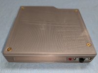
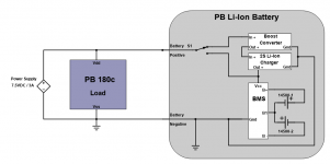
Not sure if this is most appropriately posted in this forum or over in Hacks, but I think it's more likely to reach the target audience here As a follow up to my recent Duo Li-Ion battery project, I've been working on a suitable Li-Ion battery replacement for the M5417, M5463, and M5464 NiCd packs used in the PowerBook 140 - 180c. I'd foolishly surmised that, due to the nicely compatible voltage ranges, this would be a walk in the park compared to the Duo project. When will I learn... The trick here is packing a Lithium-suitable CC/CV charger inside the pack, but only powering it when plugged into A/C power and preventing it from back feeding off of the pack itself the rest of the time. Severely complicating matters is the fact that the charge and discharge ports are the battery's same two + / - contacts. There are any number of "power path" ICs designed to solve this charge / discharge switcheroo, but they assume the load output and the charge input are separate paths.
This didn't manifest as a problem when designing a pack for the Duo because its charger sends ~20vdc to the battery (which is intended to get pulled down by the NiMh once inserted). The battery-pack-internal Li-Ion 3S CC/CV charger I used requires ~13.5vdc to engage, so when AC is disconnected, it can't back feed off of 3S 18650 cell network that, at most, outputs 12.6vdc. Had I tried the same approach here, the first problem would be a 2S Li-Ion charger needs at least 8.4vdc to function (vs. the PowerBook's 7.5vdc wall adapter output). Once fronted by a boost converter, the second problem would be that, due to the common charge / discharge path, there's no way to prevent the following: Li-Ion cells -> boost converter -> charger -> cells.... in a vicious, parasitic drain cycle that would have the BMS kicking in at low-voltage cutoff in no time.
A more sophisticated, current direction sensing approach is needed that works properly in all of the following scenarios:
Those last 2 may seem obvious or unnecessary, but some of the circuits designs I devised seemingly worked fine for scenarios 1-3, but wouldn't disengage the charger in the case of situation #4 for instance. Anyway, here's what I've come up with:
The sensing / steering is managed by an Analog Devices LT1494 precision OpAmp, and the following is a brief description of what's happening in each of the 5 scenarios outlined above:
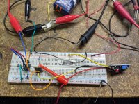
Here's a shot of the circuit above on a breadboard doing what it's supposed to do.
And last but not least, here's the finished article with the steering circuit crammed onto a small perf-board between the charger / boost converter sandwich (left) and BMS (right)...
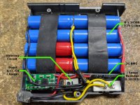
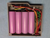
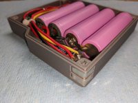
The battery my 180c had in it when received was an aftermarket pack that just screwed together, which was really quite convenient! I'm using 8 x 800mAh 14500 3.7vdc Li-Ion cells (2 serial banks of 4 cells), which are a perfect lengthwise replacement for the OE NiCds, but leave a bit of space on top (hence the strips of rubber tape to keep things from rattling). If someone made a 16500 (16mm diameter vs. 14mm) cell with a bit more oomph, that would be just the thing! I suppose at 3.2Ah (800mAh *4) though, I shouldn't complain. I've been running the pack as pictured for a couple of weeks now with no issues. Happy to post a BOM if anyone is interested
Not sure if this is most appropriately posted in this forum or over in Hacks, but I think it's more likely to reach the target audience here
This didn't manifest as a problem when designing a pack for the Duo because its charger sends ~20vdc to the battery (which is intended to get pulled down by the NiMh once inserted). The battery-pack-internal Li-Ion 3S CC/CV charger I used requires ~13.5vdc to engage, so when AC is disconnected, it can't back feed off of 3S 18650 cell network that, at most, outputs 12.6vdc. Had I tried the same approach here, the first problem would be a 2S Li-Ion charger needs at least 8.4vdc to function (vs. the PowerBook's 7.5vdc wall adapter output). Once fronted by a boost converter, the second problem would be that, due to the common charge / discharge path, there's no way to prevent the following: Li-Ion cells -> boost converter -> charger -> cells.... in a vicious, parasitic drain cycle that would have the BMS kicking in at low-voltage cutoff in no time.
A more sophisticated, current direction sensing approach is needed that works properly in all of the following scenarios:
- Pack installed and providing power (discharge)
- Pack installed and charging from AC (charge)
- Pack removed from unit. No charge or discharge (idle)
- Pack installed and charging, then toggled to discharge (e.g., AC power removed)
- Pack installed and discharging (or idle), then toggled to charge (e.g., AC power connected)
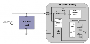
Those last 2 may seem obvious or unnecessary, but some of the circuits designs I devised seemingly worked fine for scenarios 1-3, but wouldn't disengage the charger in the case of situation #4 for instance. Anyway, here's what I've come up with:

The sensing / steering is managed by an Analog Devices LT1494 precision OpAmp, and the following is a brief description of what's happening in each of the 5 scenarios outlined above:
- Current flows out of the pack through D1. The gate of N-channel MOSFET Q1 is pulled low by R2 (10K Ω) and remains disengaged by LT1494 due to current flow from - to + across R1. Charger is off.
- Current flows across R1 from + to - causing LT1494 to pull Q1's gate high, thereby allowing current to flow from Source to Drain. Charger is on.
- Similar to #1. No flow across R1 so LT1494's output & Q1's gate remain low via R2. Charger is off.
- Once current stops flowing from + to - across R1, R2 pulls Q1's gate low. Takes about 1s with a 10K resistor at R2.
- This one was a bit of a puzzle. Even with power applied, D1 prevents current from flowing into the battery (as it should since only the CC/CV charger has any business charging the cells) and with Q1 off, there's no current flow across R1 for the LT1494 to sense and turn Q1 on (Catch 22). Enter R3 at 100K Ω. Once plugged into AC, a nominal current flows from battery + to battery - through R3 and across R1, thereby inducing LT1494 to energize Q1's gate and turn on the charger. Unfortunately, R3 remains when not plugged in and with the pack removed, so there's permanent, small parasitic drain. Left long enough, it'll eventually drain the cells to the point that the BMS intervenes and shuts down so if someone has a better idea, I'd love to hear it! That said, it'll take nearly 5 years to drain with a 100K Ω R3, so perhaps not a material concern
Here's a shot of the circuit above on a breadboard doing what it's supposed to do.

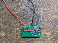
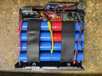
And last but not least, here's the finished article with the steering circuit crammed onto a small perf-board between the charger / boost converter sandwich (left) and BMS (right)...

The battery my 180c had in it when received was an aftermarket pack that just screwed together, which was really quite convenient! I'm using 8 x 800mAh 14500 3.7vdc Li-Ion cells (2 serial banks of 4 cells), which are a perfect lengthwise replacement for the OE NiCds, but leave a bit of space on top (hence the strips of rubber tape to keep things from rattling). If someone made a 16500 (16mm diameter vs. 14mm) cell with a bit more oomph, that would be just the thing! I suppose at 3.2Ah (800mAh *4) though, I shouldn't complain. I've been running the pack as pictured for a couple of weeks now with no issues. Happy to post a BOM if anyone is interested
Last edited by a moderator:

