Mustermann
Well-known member
As you may know, a LC475 lives with me.
My current target is to operate that LC at 40Mhz, so I read some pages about ROM hacking and MEMC chip.
From the schematic I know LC475/P475/Q605 are using programmable Gazelle clock generator chip.
Based on schematic and that document I learned that Gazelle is connected to MEMCjr and pins can be controlled thru a register in MEMCjr (Clock Generator Register at $F98003C0)
https://68kmla.org/bb/index.php?threads/wombat-650-800-board-overclocking-limitations.38538/page-11 #210
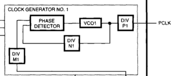
MEMCjr documentation is stating that Gazelle is in general a Sierra Semiconductor SC11412 dual programmable clock generator.
So i read thru the SC11412 datasheet and found that it is loading a basic clock divider at startup based on the level of some inputs (those we are changing with moving resistors)
But it can be programmed as well.
As all of the relevant pins can be controlled by MEMCjr I tried to poke those pins to change setting of Gazelle.
IT WORKS!
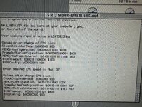
I Poked these values:
$F98003C0->$00 ; Tristate clock interface
$F98003C0->$08 ; Set MEMCjr pins to output, set lines to b00
$F98003C0->$0C ; Reset Gazelle Register and load from input lines
$F98003C0->$08 ; Return to normal (as I do not want to send data)
$F98003C0->$00 ; Tristate clock interface
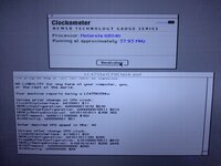
Should ask Gazelle to load the config of both resistors connected to GND = 20Mhz
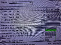
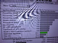
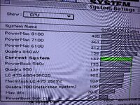
Checked with Norton Sysinfo: 83% of before
I Poked these values:
$F98003C0->$02 ; Tristate clock interface
$F98003C0->$0A ; Set MEMCjr pins to output, set lines to b10
$F98003C0->$0E ; Reset Gazelle Register and load from input lines
$F98003C0->$0A ; Return to normal (as I do not want to send data)
$F98003C0->$02 ; Tristate clock interface
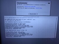
Should ask Gazelle to load the config first resistor connected to GND and second resistor connected to 5V = 33Mhz
Checked with Norton Sysinfo: 137% of before
Based of the documentation of SC11412 I assume that we can upload a customized configuration as well which is expected to choose one of a big bunch of clock frequencies.
So neither soldering nor spicy-o-clock is needed to overclock LC475/P475/Q605

