• Updated 2023-07-12: Hello, Guest! Welcome back, and be sure to check out this follow-up post about our outage a week or so ago.

Need guidance on Classic II repair

sixsevenco

Well-known member
Hi Everyone,

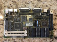
My Classic II arrived!  Cosmetically, it's beautiful, but it definitely needs recapping.  The electrolyte fluid leak is very obvious.  I don't see any corrosion, so that's good.

Anyway, I have tried to do my homework, and figure as much of this out as possible.  But I've hit a point where I am stuck, and I could use some help.  My board has 13 capacitors.  Looking at the reference for my board at maccaps.com, I see that I need to buy the following replacements capacitors:

8 - 10µf - 16V - SMT
3 - 47µf - 16V - SMT
2 - 1µf - 50V -SMT

First Question:  For the first capacitor (10µf - 16V - SMT), there are 887 options on Digikey that meet these specs.  How do I narrow this down to a specific capacitor to buy?  Do I need to worry about tolerance? Dimensions?  Or should I just go with the lowest price?

Second Question:  Should I recap the power supply while I'm at it?  The caps on the power supply seems to be through hole, so that will likely be an easy task...

Third Question: I've read that there is a bleeder that should discharge the CRT.  Any chance that isn't working as intended?  I've never worked with CRTs before, so I'm a little intimidated. 

Fourth Questions: Are there any guides on how to service/lubricate the floppy drive?  I haven't found any.  (admittedly, I haven't looked that hard.)

Thanks

67


sixsevenco

Well-known member
First Question Answered...  In another post, it was recommended to get a kit from trag.  I've sent him an email.

Any guidance on my remaining questions? bw:)


Bolle

Well-known member
2# You definetly should. Classic/Classic II analog boards are prone to break down due to leaky caps.

3# It can fail. Regardless of that I always do a manual discharge if I have to remove the anode cap. I never had it fail yet but better be safe.

As long as the work I am doing in there does not involve taking the anode cap off there is no need for discharging if you ask me.

 
Last edited by a moderator:

MOS8_030

Well-known member
First Question:  For the first capacitor (10µf - 16V - SMT), there are 887 options on Digikey that meet these specs.  How do I narrow this down to a specific capacitor to buy?  Do I need to worry about tolerance? Dimensions?  Or should I just go with the lowest price?

67
Start by filtering "active". Then "tolerance". %20 is generally acceptable for these systems. Then try to determine the dimensions of the component you want to replace.

Also if you can read the PN on the existing component you can usually google up a reference.


sixsevenco

Well-known member
Thank you to everyone that has responded so far.  I'm off to the races!  (Well, I'm actually not racing.)

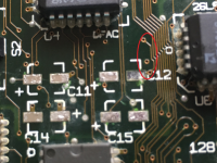
I removed all the caps, and next step is to clean the board.  That being said, I have a problem.  I was a careful as I could be, but I ended up lifting a pad for capacitor C12. I need some guidance on how to work around this.  According to the wiki, I can use a wire to work around this, but I'm not sure how.  Any help is greatly appreciated!!!

What happens if you DO lift a pad? We've all done it lots of times. It happens. Don't panic. Often times it's as simple as applying a tiny amount of super glue underneath to reattach the pad. But if the pad has completely come off and is no longer electrically attached, follow the trace on the circuit board that it used to be connected to, until you find a place where you can solder a small wire. Do so, then cut the wire to length and solder the other end to your new cap.


IMG_0822.JPG


sixsevenco

Well-known member
So, I'm trying to figure this out.  I think I am making progress, but I would love for someone to confirm if I am approaching this correctly.

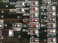
It appears to me that missing the C12 pad trace leads to C52 on the other side of the board.  I've tested for continuity with my multimeter.  As a solution to the missing pad, I think I need to solder a wire to the negative terminal on the replacement C12 capacitor, and wrap it around the board and attach to C52 in my picture below. Is that correct?  Is there a diagram somewhere that could verify this?

Any responses are appreciated.  Even if I don't get a response, I'm also trying to document my problem, and hopefully the solution to help others in the future.

C12.png

C52.png


Bolle

Well-known member
Solder some really fine wire to one of the two vias instead. No need to wrap a wire around the whole board.


sixsevenco

Well-known member
Solder some really fine wire to one of the two vias instead. No need to wrap a wire around the whole board.


Thank you!  Are the vias conductive? That was my first thought as well. I tried them with my multimeter probes and got no response. I assumed they had some sort of coating on them...


Bolle

Well-known member
If there is coating on there carefully scrub it away. If your wire is fine enough to go inside the via you should get away without removing any of the protective layer. Your probe probably did not reach far enough into the via to make contact with the tiny copper inlet.


sixsevenco

Well-known member
Solder some really fine wire to one of the two vias instead. No need to wrap a wire around the whole board.
So I finished my recap of the motherboard.  I didn't have any fine wire, so I wrapped around the MB.  It looks terrible.  I've ordered a better soldering iron and some 0.02mm wire from Amazon.  I'll see if I can get it cleaned up.  :smiley:

When I tried things out, my Classic II still wouldn't boot.  In fact, it wouldn't do anything.  At first the fan wouldn't spin, but eventually that started to work... The analog board need attention.  No that I've removed it, there is visible leakage.  I've removed the caps from the usual suspects:

CP2
CP6
CP7
CP8
CP9
CP10
CP12
CP36

Questions:

  1. I'm building my shopping list for mouser.com.  Ideally, I would like to place one order to minimize shipping costs.  I've seen in other posts that I should replace diodes DP3 & DP4.  What else should I replace?  There are other capacitors on the board, but it seems that people only really talk about replacing the 8 above.  Other's have different labels, like CF3.  Is that not a capacitor?  Or is it something else?
  2. Can I use CRC Electronic Cleaner to clean the analog board?  Will the wetness from the cleaner cause problems with any of the components on the board?  Speaker perhaps?
  3. Does the Classic and Classic II share the same analog board?  My board has a label "Mac Classic Analog Board" on the bottom side.  The part number is 630-0525.  Made in Singapore. I have no reason to believe it is not the board that originally came with the computer, but I guess it could have been replaced...
  4. This is a total NOOB question, and it will reveal my lack of knowledge on electrical circuitry.  I may not be understanding things correctly, but in other posts I think I've seen comments about tuning/adjusting voltage or perhaps some other adjustment that is needed to the analog board.  I'm I not understanding this correctly?  Or will I need to perform some sort of adjustment after recapping it?  Any help here is appreciated...
I will continue to report back any progress and successes to help any future liberators, including a full capacitor list for my analog board.  This forum has been a great help, and I would like to contribute back as best as possible. 


tanaquil

Well-known member
I can't answer any of your other questions due to equal lack of experience, but to #4, adjusting the pots (= the little turning things on the analog board) for voltage, video, etc., happens after you have made any necessary repairs to the analog board and reinstalled the board in the computer. Larry Pina's Compact Mac Repair Guide describes the adjustment process in detail. pdfs are floating about the net and the paperback book is also widely and cheaply available (ebay, abebooks).

You may want to shop in advance for appropriate TV tuner adjustment tools (plastic preferred, since many adjustments have to be done with the power running, but you'll need good strong plastic). Don't make my mistake and turn one of the pots so far that it gets permanently stuck in that position! Gently does it.


sixsevenco

Well-known member
I can't answer any of your other questions due to equal lack of experience, but to #4, adjusting the pots (= the little turning things on the analog board) for voltage, video, etc., happens after you have made any necessary repairs to the analog board and reinstalled the board in the computer. Larry Pina's Compact Mac Repair Guide describes the adjustment process in detail. pdfs are floating about the net and the paperback book is also widely and cheaply available (ebay, abebooks).

You may want to shop in advance for appropriate TV tuner adjustment tools (plastic preferred, since many adjustments have to be done with the power running, but you'll need good strong plastic). Don't make my mistake and turn one of the pots so far that it gets permanently stuck in that position! Gently does it.
Thanks my friend.  :)   This makes sense.  Thanks for the tips.  I feel better about this one...


sixsevenco

Well-known member
So I've recapped the motherboard and analog board.  My Classic II is still as dead as when I got it.  I think I'm at the end of my technical know-how in solving this.

When I first got this computer from eBay, I turned it on just to see what would happen.  At first, it was completely dead.  I toggled the power switch a few more times, and it started to come to life a little bit.  The fan struggled to move, but eventually spun up.  I never hear the hard drive spin up.  Not sure if that's because it's dead, or because it's not getting any power.  The display showed no sign of life either.

Fast forward.  I've cleaned and recapped both the MB and AB.  I was hopeful that the Classic II would show more sighs of life, but it did the exact same thing.  Fan struggled to spin, but eventually started to move.  No signs of life anywhere else.  If I'm not seeing any signs of life, I'm thinking the AB is the culprit.  Any thoughts?

Cosmetically, this Classic is in really good shape.  I also have the original manuals and box with matching serial number.  From a collectors standpoint, it has the potential to s a nice unit.  Any thoughts on how to proceed?  Should I try to locate another AB?  Or is this one reparable?


dochilli

Well-known member
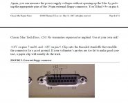
Look at the voltages at the floppydiskport. Se attached Picture. They must be 5, 12 and -12V (minimum 4.85 and 11.85).

Control the solder points of the power cord connector. I had an analog board where all three were broken.

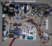
Replace TDA4605, CNY17G, IRFBC40 (picture 2).

Read "Mac Classic & SE. Repair and Upgrade Secrets" from Larry Pina.

Read this thread (and the included links):


Martin

Voltages Floppy Port.jpg

Macintosh Classic Analog Board.jpg


dochilli

Well-known member
From where are you? Europe? 230V? Look at the rear of your classic! Is it a 110V Version? And control the fuse! I made this mistake to plug a 110V version into 230V. For 5 minutes the classic worked and then the fuse blew and some other parts were defect.

 
Last edited by a moderator:

bibilit

Well-known member
  1. Does the Classic and Classic II share the same analog board?  My board has a label "Mac Classic Analog Board" on the bottom side.  The part number is 630-0525.  Made in Singapore. I have no reason to believe it is not the board that originally came with the computer, but I guess it could have been replaced...
  2. This is a total NOOB question, and it will reveal my lack of knowledge on electrical circuitry.  I may not be understanding things correctly, but in other posts I think I've seen comments about tuning/adjusting voltage or perhaps some other adjustment that is needed to the analog board.  I'm I not understanding this correctly?  Or will I need to perform some sort of adjustment after recapping it?  Any help here is appreciated...


Basically both AB boards can be swapped easily or little work, the only difference being the connector to the CRT, both have the same label (Mac Classic Analog Board)

Dochilli is right here, first step is to have a look at supply voltages.

A lot of things can be wrong with those Boards (TDA4605, CNY17G, IRFBC40 are just a few of them, the two Diodes DP3 and DP4 (1N4148) are almost bad everytime)

Keep in mind that you are dealing with live electricity.

Concerning adjustment, this is not required most of the time, and if something else is wrong the tuning won't work (PP1)

 
Last edited by a moderator:

sixsevenco

Well-known member
Apparently the optocoupler is prone to failure on this A/B.

c
Is this something that I should replace?

Look at the voltages at the floppydiskport. Se attached Picture. They must be 5, 12 and -12V (minimum 4.85 and 11.85).

Control the solder points of the power cord connector. I had an analog board where all three were broken.

Replace TDA4605, CNY17G, IRFBC40 (picture 2).

Read "Mac Classic & SE. Repair and Upgrade Secrets" from Larry Pina.

Read this thread (and the included links):
My voltages on pins 6, 7, and 8 appear to be low.

Pin 5 = -12.02

Pin 6 = 4.23

Pin 7 = 11.46

Pin 8 = 11.46

"Control the solder points of the power cord connector."  What do you mean by "control"?  Does this mean replace/reflow?  Sorry for the noob question. 

I will look into replacing TDA4605, CNY17G, IRFBC40

From where are you? Europe? 230V? Look at the rear of your classic! Is it a 110V Version? And control the fuse! I made this mistake to plug a 110V version into 230V. For 5 minutes the classic worked and then the fuse blew and some other parts were defect.
US. Sorry.  I'll update my profile.  By "control the fuse", do you mean I should replace it?  Sorry.  I've not seen the word "control" used this way before.  :blink:

A lot of things can be wrong with those Boards (TDA4605, CNY17G, IRFBC40 are just a few of them, the two Diodes DP3 and DP4 (1N4148) are almost bad everytime)
I just replaced diodes DP3 and DP4.  It seemed like there was some slight improvement/change.  The fan spun up immediately instead of sputtering for a bit first...  No other improvements.

 
Top