• Updated 2023-07-12: Hello, Guest! Welcome back, and be sure to check out this follow-up post about our outage a week or so ago.

Macintosh Plus Logic Board Troubleshooting Help - Long Chime

Thank you to everyone that helped me get the analog board working after chasing down and replacing 5 parts (other than capacitors). On one of the tests I ran (https://68kmla.org/bb/index.php?thr...-help-r2-and-r3-burning-up.44175/#post-485518) the board made this long chime and I haven't been able to get it to do anything else since then. My guess is that at some point an over voltage may have been sent down the board but I am not sure. When I start the Mac I get this extended chime that does finally stop. I am getting nothing on the screen even if I turn the brightness way up (although I can hear the high voltage running and see the glow of the filament in the tube). Using my oscilloscope it seems as though the processor is running and the ROMs are being read. I am not seeing much on the video out from the logic board and only seem to have horizontal sync. Please note I recently bought the oscilloscope so my knowledge here is limited.

I had read in a few posts that the 74LS166 ICs in U10F and U11F could be faulty and noticed they were tied to ground on PIN6 (CLOCK INHIBIT) so I pulled them out to see if that would change anything but still received the long extended chime. I didn't see any other other LS chips tied to ground on any other pins so my thought was perhaps one of them went bad. I don't have a working board to cross reference so it was a shot in the dark.

I've attached a video with the chime in case anyone has heard it before.

As always thank you for any tips to follow!
 

Attachments

  • IMG_0766.mov
    38.9 MB
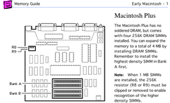
You seem to have no RAM in bank A, bank A has to be filled first. Memory detection is not automatic so you will have to set the resistor jumpers too to match what RAM you have. Unexpected RAM configurations can lead to very unusual behaviour.
mac-plus-memory.png
 
You seem to have no RAM in bank A, bank A has to be filled first. Memory detection is not automatic so you will have to set the resistor jumpers too to match what RAM you have. Unexpected RAM configurations can lead to very unusual behaviour.
View attachment 56570

HI! Thank you for pointing that out! I had removed some RAM to troubleshoot and I was trying all different combinations just to see if I could get different behavior. I will try again later with the original RAM to confirm if there is still an issue. The resistor is clipped and I assume it was running 4MB but I was never able to get it to boot so I am not sure. I have two sticks a 1MB SIMMs in the Mac Classic I just fixed up. I know those work so I can install those into BANK A to confirm it isn't a RAM issue.
 
HI! Thank you for pointing that out! I had removed some RAM to troubleshoot and I was trying all different combinations just to see if I could get different behavior. I will try again later with the original RAM to confirm if there is still an issue. The resistor is clipped and I assume it was running 4MB but I was never able to get it to boot so I am not sure. I have two sticks a 1MB SIMMs in the Mac Classic I just fixed up. I know those work so I can install those into BANK A to confirm it isn't a RAM issue.
Unfortunately it doesn't seem to be RAM related as I put all four original sticks back in and get the same thing. I tried 1MB sticks from a classic and saw the same thing. Thank you for your suggestion though!
 
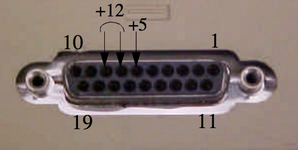
How are the voltages. You can measure these either from the motherboard connector or from the floppy port. 5V from pin 6 and ground shell.

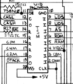
If your 15.66Mhz is correct you can trace that down to the TSM ic. Thats where many of the main clocks are generated.
You should be able to verify the 8,4,2,1 MHz clocks from here.


1684238790363.png


The sound data comes from VIA U11D to the sound IC and is clocked by VSYNC

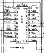
1684239162964.png

VSYNC is generated by LAG , based on the master clock and 1MHz from the TSM

with the scope you might be able to check these and make sure they are within spec.


Floppy Port Voltages.png
 
How are the voltages. You can measure these either from the motherboard connector or from the floppy port. 5V from pin 6 and ground shell.

If your 15.66Mhz is correct you can trace that down to the TSM ic. Thats where many of the main clocks are generated.
You should be able to verify the 8,4,2,1 MHz clocks from here.


View attachment 56621


The sound data comes from VIA U11D to the sound IC and is clocked by VSYNC

View attachment 56622

VSYNC is generated by LAG , based on the master clock and 1MHz from the TSM

with the scope you might be able to check these and make sure they are within spec.


View attachment 56620
Thank you for your thorough suggestion. The voltages are checking out all in spec so I don't think I have a analog board issue anymore. Checking the TSM I am seeing:

PIN 1 - 15.6mhz
PIN 2 - 15.6mhz
PIN 3 - 7.94mhz
PIN 4 - 22.2khz
PIN16 - 1mhz
PIN17 - 5.2mhz
PIN18 - 2mhz
PIN19 - 2mhz

For the LAG:
PIN 1 - 15.9mhz
PIN13 - not stable
PIN14 - 22.3kHz
 
Top