• Updated 2023-07-12: Hello, Guest! Welcome back, and be sure to check out this follow-up post about our outage a week or so ago.

Macintosh Plus Analog Board Q12 replacement

macalle69

Well-known member
Yes Techknight I do not know if this trick works on international board , as I previously swapped the original  scr E0122 YA  from this 120V American Analog Board and installed on my international analog board with faulty scr bourned.

Then I have tried directly on the USA analog board with missing SCR , I have tested several SCR before but unsuccessfully.

Hope this could be of great assistance for everybody (like You) :)


techknight

Well-known member
Well you may have unlocked the secret. Nothing wrong with that! 

Gotta see which pin that center pin is in the datasheet so I can figure out what part of the circuit this resistance was added to so I can better understand its now added purpose/change. 


techknight

Well-known member
So I figured it out. macalle69 you in fact did unlock the secret. 

I have been comparing datasheets from old SCRs to modern SCRs, the threashold voltage and current for triggering is the same. Except for one thing. the load impedence is an order of magnitude more on the old SCRs than on the new SCRs. So when you do the math, to match impedence, that means the old SCR requires 2mA of threshold at 10Ohms, whereas the newer replacements are 200uA at 10ohms. old SCRs are 200uA at 100Ohms. an order of magnitude off. So what this actually means is the circuit is latching the SCR too early as the current across the 2N3906 transistor is ramping up.

So by increasing the gate impedance, you require more voltage to trigger the gate. The more resistance you add, the more voltage/current its going to take to trigger the SCR. Precisely what we want. 

Thats my view at this point. Yall will have to experiment more to see if my theory is correct or way off base here. 


ochim

New member
Hi! I just bought macintosh+ and it also has blown fuse and Q12 EO122.

Did I get it right that there's 2 ways yo fix it?

1. Change it to brx45 and add 1k 1/4w resistor into central pin like macalle69 did or

2. Change it to brx49 and replace R50 with 1k1-1k2 resistor

Many thanks for your help!

I have't checked if there's something else broken yet, just wanted to get this clear to me.


macalle69

Well-known member
Hello Ochim

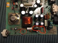
don't understand if you have international 240v analog board or US 110 V analog board, I'm pretty sure there is something else shorted , you better check and take measurements before burning one more time Q12 , if fuse blow there is a short .See red marked zone and check with multimeter Q11 at first , and then resistors near 

post-2590-0-26751800-1488048240.jpg


ochim

New member
Thanks Macalle69 for giving me a good start. My analog board is international 240V.

I did find that R53 and R54 were dead. About Q10 I am not sure if it is fine, as my dmm shows that b->e and e->b are shorted when tested in diode mode. C to emitter or base shows readings when minus lead is on c and OL when positive is on c.

I will continue tomorrow to check if there is more broken components.

Will you think that both fixes mentioned earlier in this thread would work for Q12 after i've founded and replaced all burned parts.

Many thanks!


Ferrix97

Well-known member
Have you also checked the diodes and the feedback circuit close to the optocoupler?

You should check the main switching transistor off-circuit, as it's connected to primary of the transformer (which is a very low "DC resistance") but that rarely fails since it's beefier on 240V boards.

As for Q12, I've had luck in the past with old BRX49 and BRX46. The older the better, the ones I've got don't require any resistor mod, they just have a different pinout.


ochim

New member
Hi Ferrix, thanks for tips, I will start to check those tomorrow.

I believe it will take time from me to find the circuits from the board so I would really appreciate if you could point me where they are actually located. 


macalle69

Well-known member
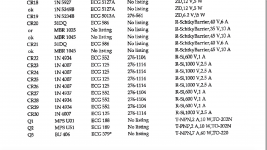
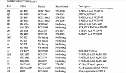
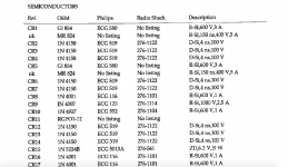
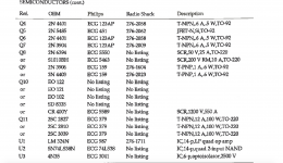
this is the international analog board parts list hope this helpful for you 

Ferrix can help you more than I can do! 

Schermata 2018-06-18 alle 23.07.03.pngSchermata 2018-06-18 alle 23.04.37.pngSchermata 2018-06-18 alle 23.06.57.pngSchermata 2018-06-18 alle 23.06.37.png


mg.man

Well-known member
Resurrecting this old thread in the hope of some advice / guidance from the pros...  I have a Mac Plus which decided to go "pop" recently when I powered it up.  Inspecting the 'board shows a blown fuse and a disintegrated Q12...

/monthly_2020_08/large.1068865899_Blownfuse(Small).jpg.2ac3f69b26ee21d6277bb15e594eea3e.jpg/monthly_2020_08/large.1736574857_Plus-Q12blowout(Small).jpg.ca92885581d64a678a2fb7bcfc0a1476.jpg

...further inspection, also seems to indicate that the insulation on the flyback transformer is gone... 

/monthly_2020_08/large.1733105559_Flyback(Small).jpg.4daa41303d7a271ab05be752f17838f5.jpg

This happened a couple of months back... and I vaguely recall finds bits of 'something' - which may have been the fragmented insulation...  A visual inspection of the 'board doesn't show anything else amiss... it's actually pretty clean.

/monthly_2020_08/large.553853060_PlusAnalogBoard(Medium).jpg.25a0be9ae2da48ae9c8fbe7885b61e11.jpg

From reviewing this thread... it sounds like I should also check Q11 - or should that be Q10?  The post refers to Q11, but Q10 was what's circled.  :-/  It also sounds like I should check R53 / R54.  Anything else?

Also... could the insulation-less flyback have caused the original blowout?  I plan on replacing it anyway (along with the RIFA), but curious if that could have been the cause... 

P.S. although clean... the 'board has obviously been repaired in the past... 

/monthly_2020_08/large.1553207791_Q6repair(Small).jpg.d2795a0cb74ab8c014ff9c7edd4bc9fb.jpg

Ooo... that C18 doesn't look too healthy... adding that to the list...  


desertrout

Well-known member
I'm feeling like this is the 'Plus Q10 / Q12' thread, so I'm going to add some additional insights here for reference. No guarantees it will make sense.

From some digging around, it would seem the determining factor in finding a working replacement SCR for this component is a very low turn off time (tq), in order for Q10 to avoid conflicting with Q11 during their self-oscillation cycle. The E0102 / E0122 have a tq MAX of 10μs, where the suggested newer 30V/0.8a replacements (2N5060, NTE5600, even the BRX44) have a tq of 10μs TYPICAL, or slower, if tq is even listed on the datasheet...

The 2N5060's and BRX's sometimes work because of production inconsistencies, and some will happen to be fast enough but it's a gamble. A resistor on the gate may also work with some as it may desensitize the circuit... but it's also a gamble without an oscilloscope for the same reason.

Unfortunately 'fast' SCR's are no longer being made as the kind of circuit we're dealing with here has been obsolete for a while. One option that still seems to be kicking around at the moment is the BR103 - there seem to be a few available (mostly on the east side of the Atlantic (https://www.ebay.com/sch/i.html?_from=R40&_trksid=p2334524.m570.l1313&_nkw=br103+thyristor&_sacat=0&LH_TitleDesc=0&_osacat=0&_odkw=br103+scr), I got mine from Germany), and they have a tq max of 6μs and I can confirm they work as a direct replacement (CGA is reverse from E01012/E0122/2N5060 with an offset gate pin, but the board is ready for it).

What I'm interested in is what we do when reliable replacements are no longer available. I'm intrigued by the idea of *making* fast SCR's with a pair of fast high-voltage bipolar transistors and some passives in SCR configuration, and something that seems to end up there in this Hackaday post: https://hackaday.io/project/168100-fat-macintosh-repair/details

This is beyond my capabilities to design (I'm no EE that's for damn sure), but the idea of breadboarding a fast SCR in this way with modern components seems like a path forward.

E01012YA datasheet

2N5060 datasheet

BR103 datasheet attached

View attachment BR103.pdf

 
Last edited by a moderator:

techknight

Well-known member
I do like that solution. Its neat, he used a specific SCR and a "clamping" circuit to prevent the SCR from false-triggering during a pulse cycle. aka, the dv/dt scenario. 

It works, and I like it. :)

Not sure if I would have figured that one out. Even though I am an EE, I am a different type of EE and these old analog/discrete self-oscillating circuits mystify me sometimes. One thing is for certain though, those particular self-oscillating switching designs are HIHGLY sensitive on the components you use. Some early Class-D Audio amplifier designs are too, MTX being one of them. change the outputs to a different type, the circuit no longer works. And the outputs are also NLA... 

 
Last edited by a moderator:

goerz

Well-known member
Hi! I just bought macintosh+ and it also has blown fuse and Q12 EO122.

Did I get it right that there's 2 ways yo fix it?

1. Change it to brx45 and add 1k 1/4w resistor into central pin like macalle69 did or

2. Change it to brx49 and replace R50 with 1k1-1k2 resistor

Many thanks for your help!

I have't checked if there's something else broken yet, just wanted to get this clear to me.
I'm resurrecting this thread because I have a problem with Q12 on an international board Mac Plus. I have a Mac Plus with a display that is too bright and the front brightness knob doesn't work.


When replacing Q12 with the same component from another working board, the problem is fixed. Since I need the other board to continue working, I looked for a replacement for Q12. I tried BRX49 and I replaced R50 (originally a 2.2K resistor) with a 1.2K resistor. All I got was no boot and a flupping set. So I used a 1K resistor and the system is kind of stable, although the brightness is unacceptably high. When I lower the brightness to normal, even with the front knob, it goes back to flupping. The voltage in the stable phase is low, around 4.7V. If I try to increase the voltage through the voltage control on the board, the Mac goes back to flupping. Should I try lowering the R50 even more? Thanks.
 

desertrout

Well-known member
Frankly, you'd be better off sourcing a BR103 on eBay - there are lots them (search for br103 thyristor or scr)
 

goerz

Well-known member
Frankly, you'd be better off sourcing a BR103 on eBay - there are lots them (search for br103 thyristor or scr)
Thank you, I'll search for one on eBay. Do you happen to know if the pinout of BR103 is reversed, the same way that of BRX49 is?
 

goerz

Well-known member
So I sourced this (relatively) expensive BR103 component, and nothing has changed: I still get a flupping set. R50 is back at the original 2.2KOhm. I put the original Q12 back, at least this way I can hear a nice startup bong, although the brightness is a bit random and the screen is wobbling. I think I have tried all I could with this board, now it's time to decide what to do with this Macintosh Plus...
 

desertrout

Well-known member
Curious. It should be a direct replacement. What happens now when you put the Q12 from the other board in (not the BRX)? And/or what happens when you put the BR103 in the other board?
 

goerz

Well-known member
Curious. It should be a direct replacement. What happens now when you put the Q12 from the other board in (not the BRX)? And/or what happens when you put the BR103 in the other board?
When I put the original Q12 from a good board the brightness issue is fixed. There are still other problems, though, because the screen flickers, and there is intermittent wobbling even with the good chip. I haven't tried putting BR103 in the good board because I'd prefer to limit the number of times I tinker with it...
 
Top