• Updated 2023-07-12: Hello, Guest! Welcome back, and be sure to check out this follow-up post about our outage a week or so ago.

Macintosh Color Classic repair adventure

agent_js03

Well-known member
Hey everyone!

Major update.

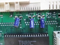
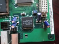
Late this morning I had a free moment so I desoldered the tantalum capacitors and removed them since they were soldered on so badly. I then proceeded to solder on some electrolytic "tin can" capacitors instead, which were a breeze to solder on compared to the tiny tantalum ones.

I also did the patch that bibilit posted about earlier, even though I didn't think it would be necessary.

I plugged it in, switched it on, and pressed the power key. Nothing happened.

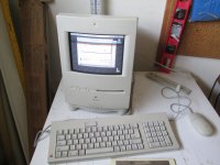
I was feeling disappointed when I did remember something that I read about in another forum. It is generally not recommended (I mentioned it earlier in this thread) but since I had nothing left to lose, I gave it a try. I unplugged my motherboard, turned the classic on, and then plugged the motherboard in. In the past, this either did nothing, or just caused the floppy drive to turn over and over. This time, I got a chime, a grey screen, and the happy mac logo, and then the little mac proceeded to boot all the way up!
IMG_0321.JPG

Naturally, this was very exciting. Up till now I haven't gotten anything from this little machine. Now I had a fully booted up working machine. Sound worked and everything. Runs Mac os 7.5.3. Whoever owned this machine before must have been in the multimedia business because it is loaded with all kinds of graphics and sound software; photoshop, Infini-D 3D graphics software, sound/midi software, the works. I played some of the composed midi files on the speaker and it worked perfectly.

So it seems that the motherboard works and everything works, the only thing that doesn't work is booting from the keyboard. I have used this keyboard with other macs and have booted from it, so I am pretty sure it works. I am at a loss as to what could be causing this to not work properly. Is anyone knowledgeable enough about the circuitry in this device that could tell me what part is involved in this? Could it be something on the analog board?


techknight

Well-known member
See if it keeps the clock ticking inside the OS or its PRAM settings on reboot. that little chip in the corner by the ADB ports is responsible for the RTC, the ADB, and the PRAM plus the power-on sequence. 

Since your keyboard and mouse works, I can only assume some of this chip is alive. 

 
Last edited by a moderator:

agent_js03

Well-known member
Ah, techknight! At last you have come to my aid.

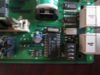
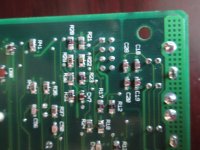
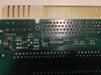
Yes, When I start up the computer I can see the clock seconds ticking, and with the new clock battery it will keep time even after it's been unplugged. So that's all well and good. My only guess is that there is something up with the connection between the ADB and the chip. I suppose it is possible that there is also an interruption somewhere in the power-on signal somewhere between that chip and the logic board connector. But from what I've heard, if there is any connection interruption of this sort, it is most likely somewhere around that chip near the ADB port. Here are photos of that area:

Top view

IMG_0323.JPG

Bottom view

IMG_0325.JPG

I would like to connection chase but I have no clue how to determine which vias go where on the other side of the board. The capacitors, etc are so dense and there are multiple layers to this circuit so I have no way of knowing. Any tips? I have a multimeter that I have used on some of the traces on top of the board and so far all the traces that I have tested have been OK. It is possible that there is just a bad soldering connection on that cap there. I did a bad soldering job before and had to redo it before the machine would even boot up at all.

Here are the other parts of the board where I put new caps on, if they are any help.

IMG_0327.JPG

IMG_0328.JPG

Honestly, at this point if I could see the wiring diagram for the analog connector I would be perfectly happy to just wire up a pushbutton to the inputs for the power on signal and just have a custom power on button without even dealing with the soft power on. I don't know if this is a safe idea or not. I just want this thing working...

Thanks in advance!


techknight

Well-known member
Find the ADB pinout chart on google, and one of them is the power-on pin. There should be continuity at that point to Pin 24 of the chip itself. If there is, then the problem is elsewhere between the chip and the standby power pin or something, But if there is NO continuity, then there is the trouble. 

Pin 26 should also connect to Pin 14 of J13-B (Edge connector)

Let me know the outcome while I go check the schematic. 

 
Last edited by a moderator:

agent_js03

Well-known member
Hey techknight.

I tested PSW to pin 24 and got a beep, connection is good there. I wasn't sure of your numbering system for J13. I touched one end of the multimeter to pin 24 of the chip and then ran the other end along the J13 edge connector. I got a beep for one of the pins. When you flip it over and hold it so that it is facing you, it is in the middle group of pins, the sixth one from the right. I doubt that this is the one that you were mentioning. Forgive my ignorance... if you can provide a little more detail in that regard maybe I can give you a better answer.


agent_js03

Well-known member
Does anyone have tips on how to trace vias? Traces are easy as they are on the same layer of the circuit and you can just look at them and see. Vias are hard because you can't see where they are going; they could be going to any layer of the printed circuit. I have thought about taking a picture of both sides and lining it up somehow, but that seems like it wouldn't be too helpful. I am wondering how other people have detected bad vias in their repair projects.


techknight

Well-known member
pin 26 to J13-B not Pin 24. 

And no, I cant provide any more detail, as I dont have any! I listed what you must perform which will tell me where to look next. 

 
Last edited by a moderator:

EkriirkE

Active member
Does anyone have tips on how to trace vias? Traces are easy as they are on the same layer of the circuit and you can just look at them and see. Vias are hard because you can't see where they are going; they could be going to any layer of the printed circuit. I have thought about taking a picture of both sides and lining it up somehow, but that seems like it wouldn't be too helpful. I am wondering how other people have detected bad vias in their repair projects.
Many times you can use a bright pen light, or flashlight and a pen or other object to cast a shadow wiggling it around a tiny bit to see where the light shimmers from the other side. Otherwise I just look for patterns in the vias (e.g. group of 3, a 4th about 1cm thaddaway)


agent_js03

Well-known member
pin 26 to J13-B not Pin 24. 

And no, I cant provide any more detail, as I dont have any! I listed what you must perform which will tell me where to look next. 
Hi techknight, what I meant was this. I know that J13 is the edge connector, I don't know what the 'B' means, or what pin 14 means (14 from the left? from the right?) so I wasn't sure how to interpret your post. That is what I meant when I asked for more detail; what I was really asking for was clarification.


agent_js03

Well-known member
Ok, so assuming that "B" refers to the second group of connections on J13, and the pin numbering alternates top to bottom, then yes there is definitely continuity between pin 26 of that chip and pin 14 of J13B.


techknight

Well-known member
Then the connections needed for the EGRET MCU to fire the machine out of standby, is ok. 

Next thing we need to check are pull-up resistors on the control lines (I will have to get back to you on this), Worst case would be replacing the EGRET as it might be bad. 


agent_js03

Well-known member
Thanks techknight.

mrpippy and EkriirkE have good advice. I was able to check a few traces successfully using the dimension method and holding it up to light, until my wife opened the garage door and called me a nerd and told me to come inside. I will continue this over the weekend.

 
Last edited by a moderator:

macalle69

Well-known member
Hey everyone!

Major update.

Late this morning I had a free moment so I desoldered the tantalum capacitors and removed them since they were soldered on so badly. I then proceeded to solder on some electrolytic "tin can" capacitors instead, which were a breeze to solder on compared to the tiny tantalum ones.

I also did the patch that bibilit posted about earlier, even though I didn't think it would be necessary.

I plugged it in, switched it on, and pressed the power key. Nothing happened.

I was feeling disappointed when I did remember something that I read about in another forum. It is generally not recommended (I mentioned it earlier in this thread) but since I had nothing left to lose, I gave it a try. I unplugged my motherboard, turned the classic on, and then plugged the motherboard in. In the past, this either did nothing, or just caused the floppy drive to turn over and over. This time, I got a chime, a grey screen, and the happy mac logo, and then the little mac proceeded to boot all the way up!

attachicon.gif
IMG_0321.JPG

Naturally, this was very exciting. Up till now I haven't gotten anything from this little machine. Now I had a fully booted up working machine. Sound worked and everything. Runs Mac os 7.5.3. Whoever owned this machine before must have been in the multimedia business because it is loaded with all kinds of graphics and sound software; photoshop, Infini-D 3D graphics software, sound/midi software, the works. I played some of the composed midi files on the speaker and it worked perfectly.

So it seems that the motherboard works and everything works, the only thing that doesn't work is booting from the keyboard. I have used this keyboard with other macs and have booted from it, so I am pretty sure it works. I am at a loss as to what could be causing this to not work properly. Is anyone knowledgeable enough about the circuitry in this device that could tell me what part is involved in this? Could it be something on the analog board?
Check continuity  on the mobo it is common  sometimes some traces are broken  see picture attached  

IMG_3664.jpg


agent_js03

Well-known member
Check continuity  on the mobo it is common  sometimes some traces are broken  see picture attached  
Hey macalle69,

The continuity there was definitely missing. I patched it as you did in the picture, and now when I switch on the CC it immediately turns on without the power button, and when I go to shutdown it doesn't power all the way off until I press the power button. I suppose this is acceptable for functioning, but could this mean something else is wrong?

Also sometimes it will just come on without a chime and there will just be a grey screen, which is a bad thing. At least I know if I want to install some kind of a custom power button, I know how to do it.

It feels like I am getting so close!

 
Last edited by a moderator:

macalle69

Well-known member
Hey macalle69,

The continuity there was definitely missing. I patched it as you did in the picture, and now when I switch on the CC it immediately turns on without the power button, and when I go to shutdown it doesn't power all the way off until I press the power button. I suppose this is acceptable for functioning, but could this mean something else is wrong?

Also sometimes it will just come on without a chime and there will just be a grey screen, which is a bad thing. At least I know if I want to install some kind of a custom power button, I know how to do it.

It feels like I am getting so close!
Hello 

the picture i have attached is referring to a repair i have done on my mobo and the connection i have done is not an universal repair , i found this broken connection on mine  , happy you have partially solved your problem but you have to check with multimeter all continuity and you'll find the broken vias so the Color classic will start and stop perfectly 


techknight

Well-known member
Thanks techknight.

mrpippy and EkriirkE have good advice. I was able to check a few traces successfully using the dimension method and holding it up to light, until my wife opened the garage door and called me a nerd and told me to come inside. I will continue this over the weekend.
This is precisely why I am not married. 


agent_js03

Well-known member
This thread has crashed, blocking off the highway for miles.
why, because of a little humor?

I have installed a custom power switch using as connections the two points that were in the picture provided by macallee69 provided. When I press it, about 50 percent of the time it chimes and boots up, the other 50 percent of the time I just get a grey screen. I am thinking of shelving this thing for a while and maybe I can do a real fix in the future.

 
Top