• Updated 2023-07-12: Hello, Guest! Welcome back, and be sure to check out this follow-up post about our outage a week or so ago.

Mac Portable, Dead Battery, Compatible AC Adapters

uniserver

Well-known member
has anyone done any more work on these Back-Lit Models?

for instance what is: and kindly what are the proper values?

VR1

Q1

Q15

Q16

Q20

IS U5L Voltage Regulator Replaceable?

U2L - Voltage Ref?

What are common issues with these?

For instance, what part would allow the hard drive to spin up solely from battery? Q16?

I'v got 2 back-lit boards here that are both acting funny when (only) running off a good SLA battery.

When plugged in both boards work flawlessly.

Please lets expand this thread with good complete info, I am sure there are some back-lit owners that could find this information very useful, looks like technight has a good start.

I can hodge podge something together, so i can get my multimeter on some of these parts to see what the values are, my only issue is, I do not have a properly working back-lit portable board for a base-line.

 

NJRoadfan

Well-known member
The 9v AC Adapter trick works and I have seen Portables being sold on ebay in the past with such an adapter rigged up in lieu of a working battery. The power circuit between the 9v battery and the 6v SLA battery is just the cover switch. The negative terminals of both batteries is wired to a common ground and the switch just switches between the 9v and 6v's positive terminal. You could even use a 6v AC adapter on the 9v battery connector if you are concerned about the step-up regulators on the motherboard. You don't need the main AC adapter to run this setup either.


uniserver

Well-known member
I am going to be working with mcdermd to try and fix these boards that people fry using powering methods other then spec.

I have 5 boards here that, pretty much from what I diagnose just need a replacement 12v boost regulator.

Will post new info as discovered.


NJRoadfan

Well-known member
Has anyone measured the amperage thats pulled from the 6v SLA battery when the hard drive is spinning up? I didn't think to do this while I had just leads running to the battery terminals. I'm curious as to how much current these circuits see with the "correct" power setup.


James1095

Well-known member
I am going to be working with mcdermd to try and fix these boards that people fry using powering methods other then spec.I have 5 boards here that, pretty much from what I diagnose just need a replacement 12v boost regulator.

Will post new info as discovered.

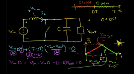
A typical boost regulator works by repeatedly charging up an inductor, then opening the switch (transistor or mosfet) so the magnetic field collapses rapidly, resulting in a high(er) voltage pulse which is directed through a freewheel diode into the output filter capacitor. If there is no load on the output, the resulting pulse can spike FAR higher than intended, so it's possible to damage the switching device in the regulator or the freewheel diode. This shouldn't happen on a *properly* designed regulator, but these things were relatively new in consumer devices during the Mac Portable era. In addition to that, ESR in the output filter capacitor can exacerbate the problem, as a good low ESR capacitor will tend to absorb the brief spike and clamp the voltage. A higher input voltage would also tend to make things worse.

You may discover otherwise, but this is my best guess at why these things are frying when powered without a battery installed. A scope on the switched side of the inductor would be a good way to see what's happening if the regulator doesn't zap instantly. A power resistor of a few tens of Ohms wired in place of the battery may also be enough to damp any spikes, or you could try installing a trans-zorb across the switching device in the regulator to protect it from excess voltage.


uniserver

Well-known member
Is there a proper way to check the inductor?

I would assume they do not normally go bad.

I feel that this method of attaining 12v,

ITs still kind of like black magic to me. :)

Battery (6.7v to 6v) ---> boost regulator(switching transistor or mosfet) ----> inductor ----> freewheel diode -----> Filter Cap -----> 12 volts ?

All the components have to work properly in the circuit… its almost like a recipe for making bread, everything has to be right.

I have a situation with 5 boards, where the multimeter will show me 11.94 volts, but as soon as i attach any kind of load to the 12v side

it collapses to nothing.

The caps are freshly installed,

Diode appears to look fine, would a normal ESR Checker/Diode Checker/meter be able to test a freewheel diode?

If you could guess as to what part might be the weak link, what would it be?

Would you consider a Diode to be a wear item? Kind of like a cap? Maybe I should change that Diode by default as well?

Sounds like those little guys do quite a bit for work.

Also I should really look at the data sheet of the Boost Regulator, to get a better understanding how that works,

It might be more like multifunction device, Switcher for the Inductor, and also a 12v regulator all in one.

witch really would make it the key for proper operation of the generated 12v rail.

i did notice this boost regulator does have quite a few legs.

Battery (6.7v to 6v) ---> boost regulator(switching transistor or mosfet part) ----> inductor ----> freewheel diode -----> Filter Cap -----> Boost regulator(12v regulator part) = 12 volt rail ?


James1095

Well-known member
It's really pretty straightforward, it's the same way a flyback transformer produces such high voltages. An inductor stores energy in the form of a magnetic field. The more quickly this field collapses, the higher the voltage it will be because it's the same amount of energy released in a shorter period of time. Each time the switching device closes, the inductor charges up by drawing current from the input. When the switch opens, the energy stored in the inductor is rapidly dumped into the load. The output voltage is regulated by a feedback loop that controls the length of time the switch is closed, which in turn controls the amount of charge stored in the inductor on each cycle.

Inductors rarely fail unless the insulation is burned off the windings causing a short. The freewheel diode can be tested like any other diode. Without a scope you are pretty much groping around in the dark but I would try replacing the regulator chip or take a look at the current limiting if it's external. Don't these use an all-in-one switching regulator IC with an internal switch transistor? As a general rule, semiconductor devices do not "wear out". Diodes can become leaky (electrically) but for the most part one that tests good is fine and there is no reason to replace it.

Definitely look for a datasheet for the regulator. The first step to diagnosing why something doesn't work is to gain a basic understanding of how it's supposed to work in the first place.


techknight

Well-known member
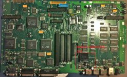
it uses a linear technology made to-220 multipin package for the boost converter. I think i made a post a year or so ago that listed the boost converter parts on a backlit board. (which mine is)


uniserver

Well-known member
trag, what symptoms was yours having?

same kind of issues?

Changing the Boost regulator fixed it?

I will try and dig up your post.


techknight

Well-known member
You need to remove the freewheeling diode and somehow insert an ammeter between that diode and the rest of the load. Because if that boost exceeds more than 1.5A or so, itll drop out. Watch the current draw.

I cant remember what all uses that 12V, I think the HDD, serial, audio, and FDD use it.

I dont know what the current rating of the inductor, or the inductance is. I could break out my B&K and measure it, but i really dont wanna tear my portable all the way apart again. lol.

You want to ring check, and inductance check the coil against a known good. That way, it can be ruled out. because if it has shorted turns it can saturate early and the voltage will drop off. but then the regulator will get noticeable hot very quickly at that point.


James1095

Well-known member
That photo is too blurry for me to make out the part number, but Linear Technology generally has good datasheets and documentation. Most of their part numbers are LTxxxx.

Inserting an ammeter anywhere in the regulator circuit is not likely to work. The current will be pulses and these circuits tend to be sensitive to stray inductance and capacitance. Without an oscilloscope, your best bet may be to replace parts one at a time until you find the bad part(s), the same thing is likely wrong with all of the boards.


uniserver

Well-known member
mouser.com

"LT1070CKC" did not return any results.

hey what do you think would be a good part# for that diode?

and the Inductor?


James1095

Well-known member
I've used the LT1070 in a couple of designs before, it's a good part.

Datasheet and documentation is here:

http://www.linear.com/product/LT1070

The CKC suffix indicates various options, stuff like temperature range, package style, whether it's Pb-free, etc. You need to start searching by the root part number.


James1095

Well-known member
the coil has to be measured.
Does it not have a 3 digit code on the top? It works the same way as capacitor codes.

You can make a pretty good guess by looking at the datasheet though. It will tell you how to calculate the optimal inductor value based on the desired input voltage and output voltage and current. RTFM :)


techknight

Well-known member
No, I posted a picture. It shows a part number of the coil, but it doesnt really ring any bells on google.

Sure you can go by datasheet, but the exact way IMHO on how they did it is by an inductance meter, but thats just my thought.

I am not entirely sure what amperage the 12V rail supplies, so im not entirely sure what the saturation current of the coil needs to be in that aspect. Of course we know the regulator tops 5A peak. So we can safely assume by using the maximum ratings boundary.

As a start, spec a coil based on the absolute maximum ratings. knowing your dealing with 6v to 7.5v input. and 12v output. But i would ring it to make sure its even bad first...

eh. whatever. lol mine hasnt failed. at least not yet.


uniserver

Well-known member
http://www.mouser.com/ProductDetail/Vishay-Semiconductors/VSSAF5L45-M3-6A/?qs=sGAEpiMZZMutXGli8Ay4kDeC%2frMhms2PGmqbeJ7O5WI%3d

Mouser Part #:

78-VSSAF5L45-M3/6A

Manufacturer Part #:

VSSAF5L45-M3/6A

Manufacturer:

Vishay Semiconductors

Description: Schottky Diodes & Rectifiers 5A, 45V, TMBS

: $0.31

maybe this?

http://www.digikey.com/product-detail/en/LT1070CT%23PBF/LT1070CT%23PBF-ND/891546?WT.z_cid=ref_octopart_dkc_buynow

$10.93 - seems quite expensive.... dammit.

how about this?

http://www.mouser.com/ProductDetail/Texas-Instruments/LM2577T-ADJ-NOPB/?qs=sGAEpiMZZMug9GoBKXZ751B%2faedqEegd7LygRit8d30%3d

Larger Image

Mouser Part #:

926-LM2577T-ADJ/NOPB

Manufacturer Part #:

LM2577T-ADJ/NOPB

Manufacturer:

Texas Instruments

Description: DC/DC Switching Converters STEP-UP VLTG REG

1: $5.97

maybe 3A would be plenty?

 
Top