• Updated 2023-07-12: Hello, Guest! Welcome back, and be sure to check out this follow-up post about our outage a week or so ago.

Mac 128k blown fuse on analog board

td75

Active member
Thanks for your suggestions. I only have a basic multimeter so can do some basic testing. Do you know where the SCR is on the power supply and any idea how I can test if this is faulty?

Also I replaced CR20 and CR21 rectifiers as they tested faulty with diode test in circuit. After replacing with new rectifiers they still show faulty with diode test, i.e. current passes both ways, but when removed from circuit they work correctly. Is this correct or is there a fault here?

 

td75

Active member
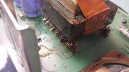
Have been testing around the rectifiers and wondering if the transformer T3 is faulty? Looks like a sticky residue on it and not sure if this is normal? Also how would I test if this is faulty?

T3.jpg


Macdrone

Well-known member
I don't know about the rectifier as they are all coated, but that huge open spot seems like its missing a big cap.


td75

Active member
Yes I removed these caps to test out of circuit, they seem okay so will be putting them back..


techknight

Well-known member
speaker is clicking because the voltage is pulsing. The power supply is tripping into overcurrent and restarting. there is an RC time constant that determines when it restarts.

Anyway, that could mean any one of the rails has been shorted, or low impedence to ground. ohm meter will tell this. I am thinking sweep circuit, maybe a shorted HOT, or floppy drive, something... could be anything.

and in rare cases, it could be a component on the primary chopper side causing false overcurrent or false start conditions, which I tend to lean more towards due to the fact that the recitifiers were shorted, could have been a lightning or a surge victim.


td75

Active member
Speaker has stopped the continuous clicking noise now. Have tested live power supply and found 170V on primary side of transformer and no voltage on any of secondary outputs. Also the speaker makes a click every now and then when testing voltage on primary side. Does this mean T3 transformer is faulty?


tomlee59

Well-known member
Thanks for your suggestions. I only have a basic multimeter so can do some basic testing. Do you know where the SCR is on the power supply and any idea how I can test if this is faulty?
Also I replaced CR20 and CR21 rectifiers as they tested faulty with diode test in circuit. After replacing with new rectifiers they still show faulty with diode test, i.e. current passes both ways, but when removed from circuit they work correctly. Is this correct or is there a fault here?
You are seeing 170 across the primary cap, so we'll assume that all is ok there for now. In general, testing of components should be done out of circuit because there can be many sneak paths that can confound measurements, as you've found. In-circuit testing is an iffy proposition. Interpreting the results correctly requires you to have studied the schematics carefully enough to understand what to expect. That's a lot of work.

The repair guide has a full schematic of the analog board, so use that to find the scr (it's a power device in a TO-220 package, so it's easy to spot). A basic test is all you can do with a multimeter, but that's still enough to find or preclude a shorted scr, at least. Measure between anode and cathode; it should read as an open circuit for both polarities. Also, between gate and cathode, you should observe standard diode-like behavior.

From your observation of clicking, I'm betting that the basic switcher core is at least healthy enough to try periodically to come up, but something is shorted across one or more supplies. The scr commonly sacrifices itself in the compacts, so I'm betting that it's at least part of the problem. If you find that it's shorted, don't stop troubleshooting and simply replace the scr. Do extra investigating to see if there's a reason it shorted (e.g, bad main switching transistor). If you only replace the scr without fixing the cause of its death, you'll just kill another one.


techknight

Well-known member
Well if you wanted to get frisky, you could pull each component and test them individually with a DMM, your sure to find it that way ;-) I know this sounds sarcastic, but theres been a few things I had repaired in the past that I had to do this, because hte failed component was manifesting itself hidden in other components. One example was an open zener that read fine in circuit as it was reading around it and not through it.

As far as SCRs go, I would check both Q8 and Q10.


td75

Active member
Have tested SCRs and they all tested okay. If I get time I may start testing each component individually out of circuit but I think repairing this has become beyond my expertise! I've spent far too many hours with this.. My brother-in-law is quite clued up in electronics so next time I see him I will ask him to take a look. I'm sure I've overlooked something simple and possibly related to original fault of shorted diodes. I hope that one day I can have this 128k running again! Thanks again for everyone's help with this :)


James1095

Well-known member
Sometimes there is no substitute for testing out of circuit, but you can check a lot of parts in place. If a diode shows a reasonable forward drop in one direction and nothing to speak of in the other then it's probably good. Transistors can be tested like a pair of end to end diodes from the B-E and B-C junction. It takes experience to know how to interpret the readings you get from some parts, but with each repair it gets a little easier.

I still remember when I first started working on CRT monitors. It was a struggle at first, but after a while they all started to look the same on the inside, and I started seeing the same 2-3 faults over and over. It got easier and easier to guess at the bad part with just a quick look at the symptoms.


James1095

Well-known member
ys hated the multisync monitors, especially sony because of thier extreme complexity.
For the most part they weren't really that bad to work on and had the same sort of faults as any other monitor. Bad capacitors, the occasional open resistor or shorted diode, blown HOT. Sometimes it was just a bad solder joint. Once I had a good multimeter and an ESR meter I had a pretty solid success rate.

The most interesting was the series of Viewsonic flat CRTs that all seemed to develop the same fault. They would come to me with a blown vertical output chip, replacing that and the fusible resistors feeding it would usually get it going again, only to fail a while later. I finally ended up tacking wires to one of the power supply outputs and using the monitor for a couple weeks with a bench multimeter connected until I finally caught the voltage creeping up. Some freeze spray found a bad opto-coupler in the power supply. It would work when cold, but eventually start to fade, causing the output to rise up until it got high enough to blow the vertical output. Once I figured that out, I must have fixed a dozen 17-22" Viewsonics with the same problem and never had one come back.


techknight

Well-known member
The problem I had with monitors, I would get them running again, just for them to scramble up and short the HOT after maybe an hour or more of operation. You knew when it was going to do it, as the screen would slowly get wider, then the picture would loose sync and the infamous squeek, tick-tick-tick-tick of the SMPS when the HOT goes short.

Replace the HOT, and it was good to go for anywhere up to another hour, to days... Never figured htat one out. It was a viewsonic if I remember correctly. I had an apple powermac 5300 do that too. would randomly short the HOT.

it was always the ones that shorted the HOT or had other random horizontal issues that drove me nuts. All the other stuff was easy.

I had an apple multiscan i think... 15" display I worked on long ago, that would pulse a bright raster with an image for the upper half the screen, then the lower half would be a bright squiggly center line almost question-mark like in striation, and almost to the burn-in point, and it would shut down. this would happen every 1 second. fire up, pulse raster, bright line, shutdown. Turned out to be a bad transistor in the pincussion circuit. Of all things, and it was on a seperate PCB near the flyback, seperate from the mainboard. (going from memory about 12 years ago, I was 15 at the time)


td75

Active member
Macdrone has very kindly sent me a 110V analog board from the US. Was wondering if there is any easy way to covert this to accept 240V or would it be best to use with a step down transformer?


td75

Active member
I've heard bad things about step-down transformers and old Macs
Didn't know about this. Do you know what bad things you heard? Would it be better to covert power supply to 240V?


Paralel

Well-known member
From what I've heard, the old analogue boards don't tolerate the fluctuations that occur with cheaper/lower quality transformers very well and develop severe problems or burn out all together in short order. So, if you are going to use a step-down transformer, it has to be excellent quality with very tight tolerances, which is not cheap.

 
Top