• Updated 2023-07-12: Hello, Guest! Welcome back, and be sure to check out this follow-up post about our outage a week or so ago.

Lisa 2/5 opinion needed!

max1227

Well-known member
Hi all,

Sorry to keep bring up my 2/5 saga but I think I may have found out what is wrong. Spoiler alert: I have no idea what I am doing so everything that follows this sentence is said with a deal of uncertainty. Unfortunately my area of speciality isn't electronics (as much as I would like it to be) so most of this was just me guessing.

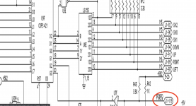
So I was looking at Lisa 1 I/O board schematics and noticed the following:

1. PWRSW sounds a lot like an abbreviation of power switch

2. J1 - 119 sounds like connector 1 on the motherboard pin 119

3. PWRSW utilises pin 119 as shown by the schematics

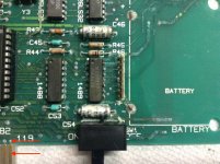
So since my Lisa starts up automatically without receiving a press from the power switch I assumed that there was a problem somewhere along anything in contact with pin 119. Turns out I get no continuity between the two red arrows on the I/O board. A simple pin path but one that is closest to the location of the battery leakage. So if 1-3 are correct and the previous sentence is correct, do you think patching this trace will start my Lisa up when the switch is pressed. In a hypothetical situation, if you were to cut that trace on a working board would that manifest as a Lisa that turns on without the soft switch being pressed. If the answer is yes then I may have the solution to my problem.

Regards,

Max
post-5944-0-03793000-1490499953.jpg

Screenshot 2020-04-24 at 23.06.03.png


sunder

Well-known member
That pin 119 you can solve by using a bit of solder, or a small jumper wire, but...

see that bar over the PWRSW? It means the signal is negated. So that means that when the power switch is not pressed there should be a +5V signal.

You can see in the schematic that there's a +5B2 going to a 3.3K R43 pull up resistor - that's I think the standby voltage from the PSU. If the trace from that line to the gate U7F is cut, or the pull up traces are cut, it's the same as if the power switch has been pressed as far as this signal is concerned. Likely the power switch just connects that line to ground, so it's normally pulled up to +5V.

But if either the pull up resistor or the signal coming out of that gate is cut, the COP421 will turn on the Lisa. That's what you're seeing.

So, likely those traces are corroded. You can see in your first picture a lot of traces are very badly corroded. If you look closely at R43 in the photo, both the left and right side show corrosion, more on the right hand side.

Cleaning those contacts and reflowing the solder might help, but likely the traces underneath are damaged. There's a lot of damage to this board, possibly superficial to the green epoxy, but once the copper is exposed, it will start to oxidize and then it will go from 0Ohms to some value and eventually to a cut trace. Over time the alkaline stuff that leaked will eat through the trace and underneath the board too.

Once you get it working try to seal the exposed areas of the PCB with something krylon acrylic coating, or whatever you can. see: https://www.allpcb.com/soldermask/soldermask_repair.html

for the pro way of doing it, but really anything that prevents air exposure, is non-conductive and lasts will work. Something like this maybe: https://www.amazon.com/Curable-Solder-Repairing-Paint-Green/dp/B01MUB4PJL

for the win.

But for now yeah, beep out all the traces you see, jumper the bad ones, reflow solder on all components that look corroded like R43, R44, the pins on that 1488 and 1489 ICs, etc. Even if they're working right now after you get the power switch fixed, they're just waiting to corrode later on.


max1227

Well-known member
Thanks for your message. So I temporarily patched the trace just to test the Lisa and the power switch now partially works. But only to turn the computer off, and when it has finished turning the Lisa off it just pings back on. So from your post (if I have understood correctly) the +5V must be getting through by other means, most likely by a corroded trace potentially around the resistors R43? Fortunately that isn't my I/O board. I just pinched a picture off the web. My is better around the resistors but worse around the bottom of the COPS chip (the traces are literally black although amazingly many still conduct). I have treated the board to hopefully neutralise the battery fluid and prevent further damage and will most likely look into some epoxy type stuff to protect what remains.

Also do you have any tips for attaching proper hookup wire? I cannot seem to get the solder to melt on the Lisa board. My solder station is 45W and can reach 450 degree centigrade but I only use it at about 320 degrees. I just can't get this older solder to melt for some reason. It melts the lead-free solder I use now easily.


max1227

Well-known member
That pin 119 you can solve by using a bit of solder, or a small jumper wire, but...


Keyboard doesn't get registered either so although my board doesn't look too bad the traces are not doing so well. But will attempt to tackle the power switch issue first.


sunder

Well-known member
Ah sorry, I was assuming that was your board. So some of what I said isn't applicable. I don't know about the solder, likely you'll have to clean it with liquid flux, I can tell you for sure they used leaded solder in the Lisa due to the age. If you're using the silver stuff, it might not mix properly and not sure if it will cause issues. The early forms of the ROHS stuff caused tin whiskers to form, not sure if that's been fixed or not, but for machines of this age, I'd try to source leaded solder, yes, I know, I know, it's toxic, but you can always wear a mask and gloves. I've got most of an old radio shack spool from the 1980s I reserve for this kind of stuff.

Generally if there's contamination, solder will not properly melt and will behave weirdly, so likely that's what you're seeing, flux will help clean it up. You probably don't need to add a lot of new solder, if anything, you'd just need to reflow the existing solder rather than add a lot more or replace it. Though I'd say, tin the legs on the chips and resistors if you can to get rid of the oxidation damage - you might be able to use silver solder for that actually since you won't be necessarily mixing it with the solder on the pads. I'd keep the temperature as low as the leaded solder needs to melt - you don't want to damage the chips or their legs, so 600'F-700'F is what you want (315'C-370'C), so 320C is pretty good, maybe bump it up a bit higher since you're heating up both the through-hole joint and the wires attached to the component. If it doesn't melt at all, but use a magnifying glass or better yet an electronics microscope camera thing to see if there's corrosion first and clean it.

It's possible the oxidation damage caused is preventing the solder from sticking, so try scraping off as much as you can with a fiberglass scratch pen, and then an antistatic brush before heating up the contacts. This is the one I bought, neither recommending it or not recommending it, just provided as an example. https://www.amazon.com/gp/product/B003NHDITW/

https://www.amazon.com/gp/product/B00880BAJE/ and https://www.amazon.com/gp/product/B00880B9TA/

Don't use sandpaper as you won't be able to control the size and it will take off a lot of PCB layers, plus they're usually made with aluminum and will leave aluminum dust behind, which if it gets under chips could potentially cause minor shorts (though that's unlikely). And yeah, don't breathe in the dust from the fiberglass pen scratches either, obviously, wear a mask and work on the boards outside on a sunny day if you can.

Some of the stuff I say is way too obvious, and that's on purpose, I tend to write these things with future readers in mind who might not know about this stuff and might wind up doing silly things, so please forgive the overly safety obvious stuff. (Plus I plan to use much of this text in the future to copy-pasta update the LisaFAQ with) :lisa2:


max1227

Well-known member
Ah sorry, I was assuming that was your board. So some of what I said isn't applicable. I don't know about the solder, likely you'll have to clean it with liquid flux, I can tell you for sure they used leaded solder in the Lisa due to the age. If you're using the silver stuff, it might not mix properly and not sure if it will cause issues. The early forms of the ROHS stuff caused tin whiskers to form, not sure if that's been fixed or not, but for machines of this age, I'd try to source leaded solder, yes, I know, I know, it's toxic, but you can always wear a mask and gloves. I've got most of an old radio shack spool from the 1980s I reserve for this kind of stuff.
No not a problem at all. Actually comparing mine to this mine is not much better. My temporary fix was tin foil cellotaped to the solder joint above to bridge the gap between it and the gold contact. I didn’t want to modify the board permanently if it wasn’t going to improve the situation. Today I decided just to trace where that pin goes and it heads to R43 as you said. The joint around R43 on the reverse of the board was not corroded and so I managed to solder to it and the gold contact at pin 119 on the other side. This is my amateur permanent solution. Yes if I did want to do a smaller more neater repair I think you may be right an application of liquid flux and light abrasion will work well.

This is where it gets weird. As per my previous message I manage to get the power switch functioning but only to turn the system off. Today I found out that if I plug the parallel cable into the built-in external parallel port the system functions perfectly. It turns on when the switch is pressed and turns off when the switch is pressed a second time. Nothing need be connected to the cable but the cable has to be present for it to work properly. The port is bent slightly facing upwards more than it should be. Could it be shorting somewhere affecting the +5V required to turn on the system?


sunder

Well-known member
This is where it gets weird. As per my previous message I manage to get the power switch functioning but only to turn the system off. Today I found out that if I plug the parallel cable into the built-in external parallel port the system functions perfectly. It turns on when the switch is pressed and turns off when the switch is pressed a second time. Nothing need be connected to the cable but the cable has to be present for it to work properly. The port is bent slightly facing upwards more than it should be. Could it be shorting somewhere affecting the +5V required to turn on the system? 


That's pretty odd. Is there anything attached to that parallel cable? the parallel port goes to VIA2, but if there's nothing attached to it, it's indicating some sort of capacity problem. Parallel cables for the Lisa are just straight through 25 pin to 25 pin, one of the pins is not used and the hole for it is plugged as a sort of keying mechanism vs serial port cables. When attached to a ProFile (or internally to a Widget), one pin called Open Cable Detect is grounded, but not when it's just a cable attached to nothing.

The thing to know about the power off is that it's handled through software on the 68000 side. So when you press the power switch and the system is on, the COP421 does not actually power off the system, instead it sends the equivalent of a keyboard press to whatever software is running on the 68000, this is triggered as an IRQ on VIA1 and accessible over VIA1. The 68k software in this case is the Lisa BOOT ROM which recognizes the power button keypress, then turns around and tells the COP421 to shut down power after doing a few things like ramping down the contrast.

So it's kind of odd that VIA2 is involved in any of this. Are your VIAs socketted? If so can you swap them around and see if anything behaves different? Not saying they're bad, but they could be, or maybe there's some weird capacitance issue preventing the communications between VIA1 and the COP421. I've seen VIAs die before, it happens, they're kind of sensitive. Swapping them and seeing different behavior is a clue that one of them has gone bad.

You can find modern replacements from the Western Design Center (can't reach their website, looks like something's up with their registrar) though you'd have to buy them from a reseller like from here: https://www.jameco.com/z/W65C22S6TPG-14-Western-Design-Center-Versatile-Interface-Adapter-via-8-Bit-I-O-Ports-14-MHz-40-Pin-PDIP-CMOS-5-Volt_2143591.html - well actually this is the CMOS version, which possibly won't work right in a Lisa, you'll have to find the NMOS version.

 
Last edited by a moderator:

max1227

Well-known member
That's pretty odd. Is there anything attached to that parallel cable? the parallel port goes to VIA2, but if there's nothing attached to it, it's indicating some sort of capacity problem. Parallel cables for the Lisa are just straight through 25 pin to 25 pin, one of the pins is not used and the hole for it is plugged as a sort of keying mechanism vs serial port cables. When attached to a ProFile (or internally to a Widget), one pin called Open Cable Detect is grounded, but not when it's just a cable attached to nothing.
It was actually just a coincidence that the Lisa did what I said it did in my previous message. But it was a very convincing coincidence as I unplugged the parallel cable (stopped working) replugged it in (started working). I did that a couple times and it repeated the former perfectly every time. Although just retested it again and it's now exhibiting a different problem. After leaving the system alone for a while it always without fail reverts back to switching on automatically. But then after a few minutes to warm up it will start working properly again. I tested the parallel cable and connector for continuity and all pins are fine.

The thing to know about the power off is that it's handled through software on the 68000 side. So when you press the power switch and the system is on, the COP421 does not actually power off the system, instead it sends the equivalent of a keyboard press to whatever software is running on the 68000, this is triggered as an IRQ on VIA1 and accessible over VIA1. The 68k software in this case is the Lisa BOOT ROM which recognizes the power button keypress, then turns around and tells the COP421 to shut down power after doing a few things like ramping down the contrast.
Thats really interesting. So actually the Lisa powering off properly does confirm that quite a lot of the system is working properly.

So it's kind of odd that VIA2 is involved in any of this. Are your VIAs socketted? If so can you swap them around and see if anything behaves different? Not saying they're bad, but they could be, or maybe there's some weird capacitance issue preventing the communications between VIA1 and the COP421. I've seen VIAs die before, it happens, they're kind of sensitive. Swapping them and seeing different behavior is a clue that one of them has gone bad.

You can find modern replacements from the Western Design Center (can't reach their website, looks like something's up with their registrar) though you'd have to buy them from a reseller like from here: https://www.jameco.com/z/W65C22S6TPG-14-Western-Design-Center-Versatile-Interface-Adapter-via-8-Bit-I-O-Ports-14-MHz-40-Pin-PDIP-CMOS-5-Volt_2143591.html - well actually this is the CMOS version, which possibly won't work right in a Lisa, you'll have to find the NMOS version.
Both VIA's are socketed so I can switch them but I would have thought since the computer does work 75% of the time after warming up I think they are probably okay. I was thinking, and again, this is just hypothetical, could it potentially be either an issue with the power supply or an issue with another trace. The power supply has the electromagnetic switch doesn't it which is triggered when the +5V drifts beyond a certain range. This power supply has had the glue on the pot removed but interestingly this supply used to be in a Lisa 2/10 where I would be continually adjusting the pot to bring the +5V back into range. However in the Lisa 2/5 it never triggers - could it be that it drifts and therefore the +5V required for startup is altered? Could it also be another bad trace? I have checked a load and as black as they are they still properly conduct (could just be the green epoxy discoloured).


max1227

Well-known member
That's pretty odd. Is there anything attached to that parallel cable? the parallel port goes to VIA2, but if there's nothing attached to it, it's indicating some sort of capacity problem. Parallel cables for the Lisa are just straight through 25 pin to 25 pin, one of the pins is not used and the hole for it is plugged as a sort of keying mechanism vs serial port cables. When attached to a ProFile (or internally to a Widget), one pin called Open Cable Detect is grounded, but not when it's just a cable attached to nothing.
Another interesting find. The resistance of the trace between Q11 and pin 20 on the COP421 chip is reading as 15.2K, is this normal?

Looking at the schematics I can’t see how this is. But as mentioned previously there is probably some component that I don’t understand how it works. But testing some other boards reveal similar readings...

 
Last edited by a moderator:

sunder

Well-known member
Another interesting find. The resistance of the trace between Q11 and pin 20 on the COP421 chip is reading as 15.2K, is this normal?
That would be U7F which looks like a 7417 NOT gate to me between its pins 1 and 2.I'd try to measure the resistance between pin 2 on U7F and pin 20 instead, and pin 1 to Q11, and pin 1 and J1-119

Hmm, actually I'm wrong, just looked it up and 7417 seems to be a hex buffer, not an inverting buffer or a NOT gate, so I got that wrong, I thought from the tip it was inverted, but yeah, that's a line infront of it, not a bubble.


max1227

Well-known member
That would be U7F which looks like a 7417 NOT gate to me between its pins 1 and 2.I'd try to measure the resistance between pin 2 on U7F and pin 20 instead, and pin 1 to Q11, and pin 1 and J1-119

Hmm, actually I'm wrong, just looked it up and 7417 seems to be a hex buffer, not an inverting buffer or a NOT gate, so I got that wrong, I thought from the tip it was inverted, but yeah, that's a line infront of it, not a bubble.
This is a really silly question but where is U7F? Is it part of the COP421 chip? 


sunder

Well-known member
U7F is in the schematic - that triangle with a line through it's nose facing left to the immediate left of the red circled J1-119 that has 2 written to it's left and 1 written to it's right.

This is a hex buffer DIP chip but you only see one of the 6 gates in the schematic. It should have 14 pins.

Assuming the 2/5 I/O board has the same layout as the Sapient Tech one (and it might not be), it's the chip immediately to the left of the bottom yellow one in this photo, right above and slightly to the left of the blue C50 capacitor. Sorry I didn't find a better handy 2/5 I/O board photo.

9ca98060b253f486785ca5e2e39f3705.jpeg.474eaf9822bb885a725de3c781198bb9.jpeg


You can sort of see it on my corroded board here right above C50 (silver can) and D9 black diode , but in there it's a 7407 and 7417, so slightly different, but they're similar in function as per http://www.ti.com/lit/pdf/sdls032

In mine there's a bodge wire you can see coming out of it. I

fcff5aecab281e7c11d1793d3c46e352.jpeg.8bfdc2c521e4ca15708885422276b195.jpeg


Last edited by a moderator:

max1227

Well-known member
U7F is in the schematic - that triangle with a line through it's nose facing left to the immediate left of the red circled J1-119 that has 2 written to it's left and 1 written to it's right.

This is a hex buffer DIP chip but you only see one of the 6 gates in the schematic. It should have 14 pins.

Assuming the 2/5 I/O board has the same layout as the Sapient Tech one (and it might not be), it's the chip immediately to the left of the bottom yellow one in this photo, right above and slightly to the left of the blue C50 capacitor. Sorry I didn't find a better handy 2/5 I/O board photo.
Fab thank you very much! I will check those pins for continuity Just to confirm is pin 1 and pin 2 the 7417? Your board looks quite good actually Lots of the traces around the COPS chip look the normal colour.

 
Last edited by a moderator:

max1227

Well-known member
U7F is in the schematic - that triangle with a line through it's nose facing left to the immediate left of the red circled J1-119 that has 2 written to it's left and 1 written to it's right.

This is a hex buffer DIP chip but you only see one of the 6 gates in the schematic. It should have 14 pins.

Assuming the 2/5 I/O board has the same layout as the Sapient Tech one (and it might not be), it's the chip immediately to the left of the bottom yellow one in this photo, right above and slightly to the left of the blue C50 capacitor. Sorry I didn't find a better handy 2/5 I/O board photo.
So I tested all those traces for continuity and they are all good measuring almost zero ohms. I also swapped the COP421 chip (no difference) and swapped the 6522's (no difference). Really not sure where to check next as all the traces appear to be working normally.

My only thought, and again, really not sure if any of this is logical thought, is that the Lisa is always on when plugged in and switched on at the wall. Therefore that +5V is running continuously when plugged in. My Lisa without fail will not start-up correctly when plugged in and switched on at the mains after a period of inactivity. However thereafter if the Lisa has been used it will always start up properly (when the soft switch is pressed). So this implies that something is changed during operation and remains because the +5V runs continuously when plugged in and mains is on. I tested this by letting the Lisa start up and then I switched it off using the soft switch but left the Lisa plugged in at the mains for an hour. The Lisa didn't start itself up again even after the components had cooled down. I don't know if I am asking the right questions however should I suspect the transistor at Q11? It utilises the +5V and is attached to the power switch trace coming of J1-119.


sunder

Well-known member
My Lisa without fail will not start-up correctly when plugged in and switched on at the mains after a period of inactivity. However thereafter if the Lisa has been used it will always start up properly (when the soft switch is pressed). So this implies that something is changed during operation and remains because the +5V runs continuously when plugged in and mains is on.
Yes, that's a clue, that smells like a capacitor somewhere, but which?

What happens when you press the power button after a period of inactivity and it doesn't turn on? Do you hear any clicking? If so that's an issue inside the power supply (voltage overflow crowbar) and usually points to one or more PS capacitors.

Does the power light light up at all?

I wonder if one of the capacitors that sit on each chip has gone bad? These are used to clean up the power fed to the chips. i.e. C52 for the COP421,

The COP421 usually talks to a muxer which is at U8E (LS153), then uses the same U7F (7417) to signal poweron on pins 12+13, C46 is involved in the RST signal sent to the COP from +16V along with R44 which should be ~47K. C36, C37, C52 are also involved with the COP, C52 is the filtering cap for the COP power, the others seem to be involved in its clock signal along with the crystal.

I'd check all of those guys.


max1227

Well-known member
What happens when you press the power button after a period of inactivity and it doesn't turn on? Do you hear any clicking? If so that's an issue inside the power supply (voltage overflow crowbar) and usually points to one or more PS capacitors.
If this is after a period of inactivity and it is left plugged in so the +5V standby is on the Lisa will always start up correctly

If this is after a period of inactivity and it is NOT left plugged in so the +5V standby is off the Lisa will always startup without the soft switch being pressed.

The crowbar mechanism is okay I think as to test this I adjusted the pot beyond the specification of +5V (probably not recommended) and it activated and the Lisa when tick tick tick tick when plugged in and power switch pressed. So the +5V is good and that safety mechanism is working normally. Ive tested a different PS and the Lisa behaves the same therefore I am inclined to believe the issue doesn’t lie within any of the caps in the PS.

Again a silly question but how does one test the capacitors? It could be one of C52 or C46 or any of the above as I haven’t checked any of those but the traces to them are good.


sunder

Well-known member
You'd need an ESR meter. Some of the newer ones will work without needing to desolder one end of the cap. Like this guy: https://www.amazon.com/Digital-Capacitor-Internal-Resistance-Circuit/dp/B0755KL87Z/
 

I bought this one, but it's no longer available: https://www.amazon.com/gp/product/B0779D67SB/

- this one returns some value which you look up on a table to see if it's within range, doesn't return the uF value, but it works in circuit which is a huge time saver.

There's also this guy, but I suspect it's not in-circuit:
https://www.amazon.com/dp/B07Y2XYTSC/


max1227

Well-known member
You'd need an ESR meter. Some of the newer ones will work without needing to desolder one end of the cap. Like this guy: https://www.amazon.com/Digital-Capacitor-Internal-Resistance-Circuit/dp/B0755KL87Z/
 

I bought this one, but it's no longer available: https://www.amazon.com/gp/product/B0779D67SB/

- this one returns some value which you look up on a table to see if it's within range, doesn't return the uF value, but it works in circuit which is a huge time saver.

There's also this guy, but I suspect it's not in-circuit:
https://www.amazon.com/dp/B07Y2XYTSC/
Fab thank you so much! I have ordered an ESR meter the same as the one you have as I really need one that works in circuit as so many of the capacitors around the COP’s chip have corroded solder joints so I cannot easily desolder them.

In the meantime I was wondering if electrically speaking a 2/10 I/O board is compatible at all with the Lisa 2/5 motherboard, CPU and memory boards? I saw a post of the Lisa FAQ which says they are but you have to make modifications to the Lite Adapter. I don’t wish to do this so if I unplug the lite adapter and leave the twiggy cables unplugged can I overcome this problem?

The reason I ask is I have seen quite a few posts saying you can switch them provided you make those modifications and then a couple saying you absolutely cannot interchange the boards.


sunder

Well-known member
I think it should work, but not 100% sure. Worst case the floppy drive will fail to work, but at least you can test power.

 
Top