• Updated 2023-07-12: Hello, Guest! Welcome back, and be sure to check out this follow-up post about our outage a week or so ago.

LCIII Recap - Apple design fault -47uF reversed!

Hi,

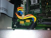
Am I the first person to discover this? C22 (the 47uF capacitor in the corner beside the power supply connector) on our LCIII has the + sign on the PCB on the negative capacitor terminal. This capacitor is between -5V and ground.

The original C22 electrolytic on this board, and on another LCIII we have here, are installed the wrong way round electronically but the right way round according to the PCB silk screen. In other words I think all the LCIIIs ever made on those two board versions went out the door with C22 polarised the wrong way!

I only discovered this because I recapped this LCIII with tantalums and after a few hour's use the -5V supply was dropping to -2.1V. Putting an ammeter in series I found the current went to about 1.3A (far more than the 75mA rating). I replaced the cap with the -ve terminal soldered where the + sign is on the board and I have no problems :b&w:

As far as I can tell the -5V supply is only for the RS422 driver chips for the Appletalk and Modem ports. Would that be correct?

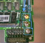
 
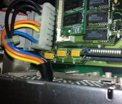
Thanks for the photos. I am saying that I am pretty sure that you have the C22 cap, the one on the left in the bottom two photos, round the wrong way.

If you put a voltmeter onto either end of C22 the way you have it, you will see that the cap should be round the other way.

I know the LCIII will work with the capacitor round the wrong way for a while but I am not sure how long.


RickNel

Well-known member
Just a query for consideration - if this is on a negative voltage rail, then would it not be correct to have the positive side of the cap connected to ground? The potential on a negative rail is supposed to be inverted, isn't it?

Rick

 
Yes Rick, you are correct.

If you are using those orangish tantalums, with the darker orange bar indicating the + side, you need to put that on the ground. So if you look at the photos uniserver posted. The one on the left hand end should face the opposite way from the other two in that row.

I find it amazing that all those LC's were produced with the C22 electrolytics round the wrong way. The only explanation I can see for why there weren't any failures is that the electrolytic failed open circuit and the capacitor in the power supply itself was good enough. There is very little load on the -5V supply.


RickNel

Well-known member
That looks like an interesting catch, but surprising that failures have not been noticed over all these years.

It could be a problem of semiotics. The + sign seems to identify polarity correctly in relation to common GND, but incorrectly in relation to potential across the specific capacitor. I wonder if the PCB designers and the assemblers apply different standards to identifying polarity on a negative voltage. Somebody here will know... :?:

Rick

 
It is a typo on the silkscreen and caps were installed the WRONG way on the two LCIII's we have (by the manufacturer)

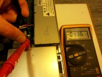
See attached photo. The meter probes have the red (+ve input to the meter) on the leg of the positive side of the capacitor. You can see it reads -4.96V.

LCIII C22 reverse voltage.jpg


Macdrone

Well-known member
Any idea what that capacitor serves? That should be checked on all the LCs correct as the board is similar with most of the caps? LCIII and up at a minimum you think?

 
The capacitor is just a smoothing capacitor on the -5V supply. I think the -5V supply is only used for the printer (appletalk) and modem port drivers. Since the aluminium can capacitors which were on the LCIII as they came out of the factory did not cause a failure I wouldn't worry about LCIIIs which haven't been recapped.

I have no idea how other LCIIIs that have been recapped have stood up. It seems that tantalum capacitors are the favourite ones to use for the recap. The tantalum that I put in facing the way the original silkscreen showed, failed by starting to go short circuit. It was dragging about 1.3A from 75mA the -5V supply and dragged it down to -2.1V. I have no idea which would have broken first, the power supply or the capacitor, if I left it going for longer. I doubt whether the Modem or Printer ports would work properly with a -2.1V supply.

Maybe the tantalums other people are using to recap their boards are more tolerant of being reverse biased.

I am not a Mac user but I was, in the early 1990's, when we made the machine which was controlled by the LCIII that I am trying to back up. So I know nothing of how the PCB layout changed with subsequent Macs.

 
Remember that on aluminum electrolytics, the polarization mark indicates the negative terminal, but on tantalums the mark indicates the positive one. As others have indicated, if this is on the -5V rail, then the + side should be to ground. Nevertheless, you should easily be able to tell which terminal is more positive with your trusty voltmeter. If you measure the voltage across the cap as +5V and the positive lead is connected to the + side of the cap, then it's installed the right way.


bbraun

Well-known member
I can confirm your results.

On my LCIII, C22's negative terminal goes to GND, and the positive terminal goes to the PSU's -5V. And the cap matches the silkscreening, meaning the positive terminal matches the + on the silkscreen.


dougg3

Well-known member
Sounds like a design mistake to me! Very nice catch, paul.gaastra. That picture with your multimeter definitely proves, IMO, that the silkscreen (and the capacitor placement) was wrong. As far as I know, and my EE coworker agrees, there should never be a negative potential across an electrolytic (or tantalum) capacitor. They've been known to make exciting bangs when installed in reverse.

http://en.wikipedia.org/wiki/Electrolytic_capacitor#Polarity

Now I'm curious about other Mac models' motherboards that might have capacitors on the -5V rail...


dougg3

Well-known member
Just found the -5V rail on my IIci on the RS-422 driver chips. There's a 47 uF capacitor near them (C5) with the negative edge hooked to -5V and the positive edge hooked to GND. So they did it correctly on the IIci for example. Yep...must just be a mistake on the LC III.


CC_333

Well-known member
Hmm... Fascinating!

However, why hasn't it manifested itself as a problem after all these years?

If this were really a bad mistake, then how come everybody's LC III logic boards haven't blown up? It seems like the LC III would've been recalled practically before being put into production if it were that bad.

Oh, well... I guess this is just further proof that there's always more to learn!

c

 
Top