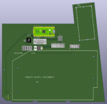
I've been working on converting one of my SEs from CRT to LCD. It all started with picking up one of @retro apple mods' excellent kits on Etsy, but that's only part of the equation. The other parts are how to power the system without the original analog board, and how to convert the monochrome TTL video to something a modern(ish) LCD will accept. I know that there are multiple ways to accomplish both of those, and I went through a few possible solutions until I hit on one I am happy with. I want a board that will mount in the place of the original analog board and slickly integrate with the rest of the system, so here's my design, which I'm calling the analogous board.
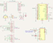
It uses guruthree's mac-se-video-converter firmware for RP2040, which I have tested on a breadboard and works excellently. I am using this panel and controller board with a 1 foot VGA cable. The barrel jack is intended for use with a 1 foot extension cable to power the LCD from 5V or 12V, selected by 0 ohm jumpers (corresponding jumpers exist on the controller board). My board has mounting holes for the SE power supply and fan in their original locations, though I still need to convert these to plated through holes. This is just a first draft, but I wanted to get it out here so that folks can see it and provide feedback.
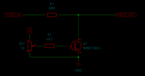
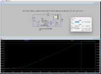
The part I'm least sure about is my brightness pot implementation. I found a 1k ohm pot that will fit in place of the original, and it works great to provide brightness control by varying the peak voltage on the VGA signal from 0.5V (quite dim) to 1.0V (quite bright, and violating the VGA spec, but the panel seems okay with it). This works well on a breadboard but I'm worried that the long traces required to implement this on the PCB will act like an antenna and result in noise on the VGA signal. Does anyone have any thoughts? I'd like to hear everyone's comments on the rest of the design too. In addition to the screenshots below, the files are out here.


Last edited:


