Put the RAMDAC back in place, the corrosion cleaned up nicely:
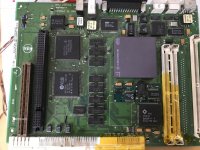
I was still getting the same artefacts as before so either the chip was bad or there was something else wrong.
I took out my working 575 board to check a few things. I started figuring out the pinout of the VRAM SIMMs to have a starting point for tracing things backwards. Then traced all connections going to and coming from the RAMDAC.
The LC475 dev note says that video data is shifted to the VRAM from the main data bus (D0-15 to SIMM 1, D16-D31 to SIMM 2). Addressing is done by the memory controller which has 9 separate video address lines. /RAS, /CAS, /WE and the clock signal for the serial output ports of the VRAM ICs are coming from the memory controller as well.
Video data is fetched by the RAMDAC through the serial outputs from the VRAM.
With all that info put together in a messy spreadsheet I started going through all the connections on the broken board.
Video address line 1 seemed to not make it from the memory controller to the SIMM sockets. All address lines traced fine to the resistor packs (acting as filters) on the back of the board, however from there VA1 did not make it's way to the sockets.
It was not a broken trace though but a faulty solder joint. I don't see how that could have happened. There was no solder on there at all. This must have been a factory error, unless someone already put their hands on the backside of that board:
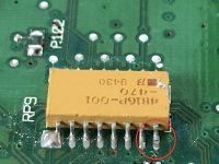
Soldered that little guy down and resoldered all the other resistor packs as well for good measure.
The result was a better, but still not completely good picture:

The lines started to fade away and come back while the machine was running, so there must have been intermittent contact somewhere or a trace with higher than normal capacity.
I went through all the serial data lines between VRAM and the RAMDAC twice. On the first time everything checked out just fine but on the second go there was one data line (luckily) not giving any continuity.
If it would not have decided to stop working right when I went for a second check I would have been looking for the problem forever... not sure if I would have done a third turn going through the same signals.
It looks like the trace connecting to the solder pad was causing the issue. I put in a short patch from the pad to the next via and got a steady beep from my multimeter now

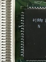
And the result:

Now that was fun


