• Updated 2023-07-12: Hello, Guest! Welcome back, and be sure to check out this follow-up post about our outage a week or so ago.

Help with SE/30

blindowl

Well-known member
So backstory. I recently got a SE/30. I knew it was working, but nothing more about the condition.

The first thing I discovered when I received it was that it was an old SE FDHD, upgraded to a SE/30.

I turned it on and noticed that the sound volume was very low. The second thing was the screen. It was very dark, even with the brightness turned to max. Also, when I adjusted the brightness, the screen flickered. There were also lot's of lighter "shadowing" going on. Time and date was also incorrect.

I turned it off and restarted a few times, then it crashed. So I turned it off again and waited a few seconds and then turned it on. The weird thing was that it didn't reboot, it went straight to the same state as before with the desktop and the crash eror message.

I turned it off again, unplugged it from the wall, waited som time and started it again.

Now chimes of death and sad Mac:
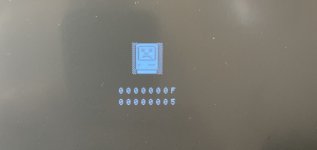
IMG_0216.jpeg

Same thing again, if I turned it off and on, it didn't reboot, it went to the same state as before I turned it off.

So, I opened it up and checked the logic board. Both the battery and capacitors had leaked, but the damage wasn't too bad (I think...).

After cleaning the board, today I did a re-cap (my first) of the SMD capacitors. I left the axial caps for now.

Now it boots to this instead:
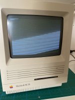
IMG_0240.jpeg

- No chime (speaker/headphone jack) - bad!
- Image looks brighter now - good!
- No screen flickering when I adjust the brightness - good!
- Checked the 5 and 12 V pins on the floppy port, they are ok - good!

It has 4 SIMMs in bank 1, and 4 SIMMs in bank 2. Not sure about their sizes. I removed the SIMMs in bank 2, but same issue. I also swapped the SIMMs in bank 1 to the ones from bank 2. Same issue. I also cleaned them with alcohol, same thing with the ROM chip.

Any advice what I should do next? I haven't tried to use the SIMMs in bank 2 only yet (if that's possible?). But what else? Where to start?

I read other posts thats it might be a RAM or ROM issue. How can I test the ROM?

 
Last edited by a moderator:

LaPorta

Well-known member
Photos of the boards would be a huge help. Also, did you re-cap the power supply, or change anything else?


blindowl

Well-known member
Photos of the boards would be a huge help. Also, did you re-cap the power supply, or change anything else?
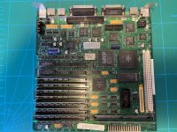
Here's the board after the re-cap (please excuse my messy soldering technique!).

IMG_0238.jpeg

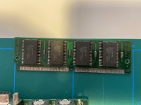
Picture of the ROM:

IMG_0237.jpeg

Battery is removed now, one of the leads on the battery holder was so damaged it broke off.

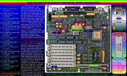
I've tested continuity on all caps according to this, and it was all good:

post-2686-0-63668700-1502804268.png

I didn't do anything with the analog board or PSU. Everything is as before, except I haven't connected its Radius display card (which shouldn't matter).

 
Last edited by a moderator:

LaPorta

Well-known member
I take it the battery exploded? There appears to be heavy corrosion in the UI and UJ series of SMDs. See if you can clean all that up/resolder them. There is also some corrosion on the  ROM pins. I see the tabs of the ROM SIMM socket are rusted: the rom socket itself may have non-conducting tabs inside, you should test all of those as well.


blindowl

Well-known member
I take it the battery exploded? There appears to be heavy corrosion in the UI and UJ series of SMDs. See if you can clean all that up/resolder them. There is also some corrosion on the  ROM pins. I see the tabs of the ROM SIMM socket are rusted: the rom socket itself may have non-conducting tabs inside, you should test all of those as well.
Yes, it looks like it exploded. I've tried to clean everything with a brush and vinegar. And then isopropanol. But the alcohol leaves a lot of white residue for some reason. I'll think about resoldering the SMD's, I just don't want to mess things up more...

Now I just inserted the ROM and then tested all pins on the edge connector with the socket's corresponding pins on the backside of the board, and there was continuity on all pins.


mac1nt0s

New member
Your recapping job looks good and I don't think that that has to do anything with the issue you're having. Sometimes those horizontal lines appear because the ROM SIMM is not making good contact. You might want to add something to keep the ROM SIMM in place (you can find some good examples here - section 6.1 and 6.2). Securing the ROM SIMM with a rubber band fixed the same exact issue for me. Let me know if it works for you too.


blindowl

Well-known member
Thanks for the advise. I've check the ROM and socket, and I don't think it can sit more tight than it already is. :(

Another thing. I just did new voltage measurements on the external floppy connector, and I have no -12 V on pin 5. What I have:

Pin 10: +5 V

Pin 8: +12 V

Pin 7: +12 V

Pin 6: +5 V

Pin 5: 0

Can that be related to the boot issue with horizontal bars on the screen, or will a faulty -12 V rail show in other ways?

-12 V is connected with the C9 capacitor, right? Maybe I messed something up there...

 
Last edited by a moderator:

joshc

Well-known member
Have you tried securing the ROM SIMM using an elastic band? It's a trick that has worked for me before.


Bolle

Well-known member
Clean the contacts on the ROM SIMM first. A fibre glass pen works really well to get rid of the corrosion.

Then check for corrosion on the contacts of the ROM socket. Only way to properly check those is with the SIMM installed and then test if there’s continuity between the solder points of the socket on the back of the board to the chips on the ROM SIMM.


blindowl

Well-known member
Clean the contacts on the ROM SIMM first. A fibre glass pen works really well to get rid of the corrosion.

Then check for corrosion on the contacts of the ROM socket. Only way to properly check those is with the SIMM installed and then test if there’s continuity between the solder points of the socket on the back of the board to the chips on the ROM SIMM.
I haven't cleaned the contacts with a fibre glass pen (only cotton swab and isopropanol), but I've already checked the continuity between the SIMM and the solder points on the back of the board. Everything seemed fine.

All replies so far suggest the issue might be related to the ROM SIMM. If contact between the SIMM and the socket is fine, any suggestion what my next troubleshooting step should be? If the issue is ROM related, that is. Can it be the ROM itself that is damaged? Is that common? It worked fine before the crash and re-cap..

I'm thinking of doing a more accurate cleaning of the board. Soak it in vinegar for some time, then clean it with soapy water plus alcohol. My previous cleaning was only on local spots, not the whole board. I'm sure it's still full of corrosion and residue.


blindowl

Well-known member
Update: after cleaning the board again, I now have sound. A very loud and clear chime (of death). First the regular chime, immediately followed by the chime of death. If this can say anything about where in the boot process things go wrong. Now I'm uncertain what do next...

 
Last edited by a moderator:

dochilli

Well-known member
Thats only a chime of death. Seems like there is a problem with the ROM or RAM. You should use the schematics to check the traces between the ROM and the connected chips (continuity test). Could be a broken trace.

 
Last edited by a moderator:

blindowl

Well-known member
Thanks, that will now be my next step. So far I have tested connectivity to UK6, D4-D19, UJ2, UI2, UJ3, UI3 and UJ4. All good so far.


Papichulo

Well-known member
I had the same problem with a powerbook 170. The thing would just go to sad mac sound even after removing the ram card. Had to replace the logic board. Mabie the board got shorted somewhere?


blindowl

Well-known member
So, I started over with my continuity check. Documenting everything so I don't miss anything, and what's left. So far:

- from ROM chips pins to ROM SIMM fingers

- from ROM chips pins to ROM SIMM connector (backside of the board)

- from ROM chips pins to UK6

- from ROM chips pins to GLU chip pins

Everything is good so far. But I will continue testing.

I also picked up a second (non functioning) SE/30. I wanted to see if another ROM SIMM or RAM would be the issue. Before I received the second SE/30 I tested the RAM SIMMS in my Mac Classic and they work fine. But I was curious to see if another ROM could help. Unfortunately the new SE/30 was in even worse condition with battery carcass everywhere... lol. Swapping ROM didn't help anyway.

Oh yeah, and now I've lost sound again :(

One thing I just discovered is that I don't get a beep on my multimeter when I measure C1. It measures around 360 ohm, to ground and J12 pin 12. Is that normal?

 
Top