GBSCSI - A cheap(er?) solution to replacement storage

GRudolf94

Well-known member
So, a while ago I designed these, and they've finally been cleaned up and tested enough for release (well, some variants):


Why: I wanted a board done my way. Figured I might as well. I can get drives for my countless janky UNIX workstations, the occasional desktop Mac PCB, and PowerBooks, all with a single design. I might be biased, but I think it's a neat design and a decent compromise between quality/layout/signal integrity, price and form factor.

At the time, standalone RP2040 2.5/3.5", Pi Pico 2.5/3.5", Pi Pico 3.5" HDD footprint and DB25 variants were designed, plus a carrier card that fits SCA connectors in workstations which I haven't yet had the opportunity to test and verify mechanics on.

Turnkey units are available from https://decromancer.ca (a friend's store, no further affiliation - I am not making money selling these).

Comments and feedback are welcome.
1712382639877.png
 

GRudolf94

Well-known member
Will be watching to see when the SCA variant(s) are avaiable!
I don't plan on integrating the SCA connector to a separate variant - not unless the carrier board doesn't work :)
Do you have some benchmarks?
Running ZuluSCSI firmware, it should bench the same - about 9ish MB/s read, if the host can go the distance. Half the devices I plan on using it for only do SCSI-1 and, as such, are stuck at 5MB/s, so no good machine for benchmarks on my end.
 

ScutBoy

Well-known member
I don't plan on integrating the SCA connector to a separate variant - not unless the carrier board doesn't work :)

Running ZuluSCSI firmware, it should bench the same - about 9ish MB/s read, if the host can go the distance. Half the devices I plan on using it for only do SCSI-1 and, as such, are stuck at 5MB/s, so no good machine for benchmarks on my end.

Carrier board is fine :)
 

stormy

Well-known member
Isn't the BlueSCSIv2 already a full featured Pico based SCSI emulator? Did it have some limitations you weren't keen on?
 

Daniël

Well-known member
Isn't the BlueSCSIv2 already a full featured Pico based SCSI emulator? Did it have some limitations you weren't keen on?

ZuluSCSI RP2040 was actually the first, fully featured Pico based SCSI emulator, with the BlueSCSI v2 being a fork of it which added on a couple of BlueSCSI V1 specific APIs/features.

GBSCSI forks ZSCSI as well, I believe the aim for GB is to provide an affordable ZuluSCSI-compatible device, with the PCB design and shape done to the author's wishes.
 

rabbitholecomputing

Vendor The First
Isn't the BlueSCSIv2 already a full featured Pico based SCSI emulator?
@stormy For what it's worth, GBSCSI2 is a hardware design that's derived from ZuluSCSI Pico OSHW board design, which is Open Source Hardware. Rabbit Hole Computing released ZuluSCSI Pico under the CERN Open Hardware License (Strict variant) version 2.0 back in October of last year. GBSCSI2 runs unmodified ZuluSCSI Pico firmware, and I find it frustrating that @GRudolf94 chose to omit this fact from his original post. Why? It's a doorstop without the ZuluSCSI firmware that enables it to be a functional SCSI-2 emulator. What's the problem with giving credit where credit is due? I have no problem with the existence of GBSCSI2, at all.

As the person whose business bankrolled the port of ZuluSCSI to the RP2040 microcontroller (which is the microcontroller used on the original Pi Pico), I feel obliged to correct what seems to be a misunderstanding about the origins of the BlueSCSI Pico firmware (aka BlueSCSI V2).

BlueSCSI Pico/V2 was announced (which uses the same exact microcontroller, but without the Pico board, as BlueSCSI V2) was unveiled ten weeks after the release of ZuluSCSI RP2040. This is not a coincidence. Nobody associated with BlueSCSI was involved with writing ANY of the firmware development/code that enabled the SCSI emulation to work on the RP2040. The BlueSCSI V2 guys

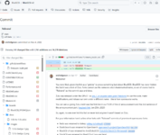
You don't need to take our word for any of this, since anyone here can see for themselves the commit where the BlueSCSI V2 guys did a mass search-and-replace of ZuluSCSI with BlueSCSI in their firmware, which was Described as a "rebrand" in the actual commit in the BlueSCSI repository from November of 2022.

It's important to me that this hobbyist community understands that without ZuluSCSI RP2040, BlueSCSI V2 simply would not exist in its current form. The hardware and firmware development cost tens of thousands of dollars, along with very extensive testing, which I was directly involved with. It's very disheartening to see endless praise being heaped on members of the BlueSCSI team for work they simply appropriated for their own ends.

The ZuluSCSI firmware itself could not exist without the huge amount of effort (and resulting code) which was previously invested in the SCSI2SD command-handling code, which was almost entirely written by Michael McMaster.

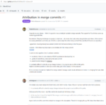
On August 12th of 2024, 531 days, nearly a year and a half later, the BlueSCSI V2 project maintainer added the following annotation to the original commit from November of 2022, stating the following:

You were likely given this link as a "gotcha" to prove something bad about BlueSCSI. BlueSCSI has never hidden the fact it was a fork of Zulu. Forks cannot use the someone else's trademarked name, so we of course had to "Rebrand" as this commit says and does.

Zulu was released under the GPLv3 - so you, I, or anyone were given freedoms to use the code, make modifications, and release our own under a different name - this is how opensource works.

You can see us giving Zulu credit was the first line in our TLDR of the v2 announcement and the 2nd sentence of the announcement part. (wayback link, Jan 25th, 2023)
While this is technically correct, nowhere did the BlueSCSI V2 "maintainers" properly credit the actual authors of the work they appropriated. In the open-source world I've been involved with for over 20 years, that's a shitty and deceptive thing to do, and in this case, there was a business case for doing so. The argument from the BlueSCSI guys seems to essentially be "We didn't do anything illegal" which in no way means that their hands are clean. They've engaged in deception from the beginning.
So, again, no one ever hid this fact or never told anyone it wasn't based on Zulu.
This is far from entirely correct. There are multiple examples of intentional obfuscations of code merged from the ZuluSCSI code base to the BlueSCSI V2 code base.
For your information here's a few other forks with "Rebrand" commits of prominent opensource forks:
As the first two examples are pure software projects, with no corresponding hardware, I'd argue that this is a red herring, intended to distract from the real issue, which is that they're commercially https://github.com/opensearch-proje...f168580ab67ab9b324aeb54f406f9a68e3b6da08c9d0a
This is absolutely correct, and also something we have never hidden in any of our commit history, unlike the BlueSCSI folks. See relevant Wayback Machine link here.
  • ZuluSCSI was renamed to BlueSCSI v2 (you are here)
The part that's conveniently left out here is that Eric and his distributors sell assembled BlueSCSI V2's, as well as kits, for money. Eric is operating a commercial enterprise, known as Helgeson Technology Services LLC. That's "running a business" and claiming BlueSCSI V2 is "not a commercial project" when you have authorized resellers globally is incredibly disingenuous, not to mention delusional.

Despite this fact, a year ago, the BlueSCSI V2 maintainer had the audacity to write the following on Reddit:
"I think mainly the difference is BlueSCSI is not a commercial project, we just give away everything, hardware, designs, etc. We don't pay contractors to write the software, we write it ourselves."
I should note that Eric is seemingly totally okay disrespecting/talking trash about the one contract developer who is responsible for nearly all of the non-SCSI2SD-related code he chose to appropriate. That's rich, folks.

They already had BlueSCSI V1. If it was so great, why did they decide they needed to start completely over with BlueSCSI V2? Maybe it was because ZuluSCSI RP2040 delivered six to eight times the throughput of BlueSCSI V1, blowing it out of the water as a massively improved solution, which cost significant amounts of time and money. It was just too tempting to leave it be.

Finally, I'd like to point out that Eric took it upon himself to administratively block my personal GitHub user account from being able to comment on, file issues related to, or initiate discussions about, anything related to BlueSCSI V2. While he certainly has the right to do this, it's a premeditated and outwardly hostile thing to do. The block has been in place since the BlueSCSI V2 source code repository became public, as far as I'm able to tell. This would seem to speak to his initial intent. I'm still blocked to this day, and I don't expect it to ever change.

1724108116330.png
 

Attachments

  • 1724104959524.png
    1724104959524.png
    275.2 KB · Views: 41
  • 1724106370458.png
    1724106370458.png
    165.6 KB · Views: 38
  • 1724107269447.png
    1724107269447.png
    274.1 KB · Views: 45

GRudolf94

Well-known member
For what it's worth, GBSCSI2 is a hardware design that's derived from ZuluSCSI Pico OSHW board design, which is Open Source Hardware. Rabbit Hole Computing released ZuluSCSI Pico under the CERN Open Hardware License (Strict variant) version 2.0 back in October of last year. GBSCSI2 runs unmodified ZuluSCSI Pico firmware, and I find it frustrating that @GRudolf94 chose to omit this fact from his original post. Why? It's a doorstop without the ZuluSCSI firmware that enables it to be a functional SCSI-2 emulator. What's the problem with giving credit where credit is due? I have no problem with the existence of GBSCSI2, at all.

My bad, not an intentional omission - I honestly expected myself to write my own SDE code at some point, but I keep being forced to realize I am not really a SW guy.
 

rabbitholecomputing

Vendor The First
My bad, not an intentional omission - I honestly expected myself to write my own SDE code at some point, but I keep being forced to realize I am not really a SW guy.
I figured. No worries! We all have our strengths and weaknesses. Thank you for your contribution!
 
Last edited:

ZaneKaminski

Well-known member
@GRudolf94 Nice work on the switching regulator layout. Looks like you kept the "hot loop" pretty small. Lots of new-manufacture gizmos don't get that right and are probably emitting a ton of EMI needlessly.

But what about those ‘245s? Those look like they're driving the SCSI data and control buses. SCSI should be generally driven open-drain i.e. you only drive the bus low but the '245 is a push-pull driver that drives high too. Newer SCSI devices have active negation where the bus is weakly driven up to the logic one level but I think your design with the 'LVT245 drives the bus high way too hard. Here's a graph of how strong you're allowed to drive the SCSI bus high (and you still have to have active-negation compatible terminators or else you must only drive low):
Screenshot 2024-09-10 at 1.34.16 PM.png
I think that 74LVT-series outputs have like 5-8 ohms equivalent series resistance so with the LVT245s at 3.3 volts and the SCSI bus at 3 volts, your drivers might put 37.5-60 mA into the bus when only 20 mA is allowed. Especially since your board looks like it has plain resistive termination and a 1117-type regulator, I think if you drive all 1's on the data bus, current will “backflow” across the termination resistors and raise up the termination voltage beyond 2.85V toward 3.3V. Then potentially the computer will not be able to drive the /ACK signal low due to increased termination current.

Other SCSI boards I've seen use a bunch of 74LVT125 buffers that only drive low so maybe it would be a good idea to switch to that buffering style.
 

saybur

Well-known member
I don't have my spec copies in front of me so this is just from memory, but I think SCSI-2 may have been less specific about the drive strengths of active negation drivers than the later revisions. Is that where the above chart came from?

The design does look to correctly run the OR-tied lines through tristate drivers that only go low, those are the ones that I would be much more concerned about. For the termination voltage issue you highlighted, it looks like the 245s should be off any time the device is not the bus driver, unless I'm missing something.

For context I don't have formal EE training, but I'm trying to learn something from this design; for the SCSI stuff I've done I stuck to the resistor pack / open collector only approaches due to concerns about violating the spec (and driving the bus incorrectly due to FW bugs), but more knowledge about alternative approaches is always good to get into the open.
 

GRudolf94

Well-known member
@GRudolf94 Nice work on the switching regulator layout. Looks like you kept the "hot loop" pretty small. Lots of new-manufacture gizmos don't get that right and are probably emitting a ton of EMI needlessly.
Thanks - I did try and pay attention to the layout, and did everything I could to keep it reasonably clean.
But what about those ‘245s? Those look like they're driving the SCSI data and control buses. SCSI should be generally driven open-drain i.e. you only drive the bus low but the '245 is a push-pull driver that drives high too. Newer SCSI devices have active negation where the bus is weakly driven up to the logic one level but I think your design with the 'LVT245 drives the bus high way too hard. Here's a graph of how strong you're allowed to drive the SCSI bus high (and you still have to have active-negation compatible terminators or else you must only drive low):


Other SCSI boards I've seen use a bunch of 74LVT125 buffers that only drive low so maybe it would be a good idea to switch to that buffering style.


Indeed, SCSI is supposed to be open drain, and each line must be able to sink 48mA. So I'm somewhat violating the spec twofold here - those buffers are only good for 32mA (but they can source 64mA).

The '245s are always enabled - in fact, there is no free I/O on the Pico that would allow me to tristate them off the SCSI bus...which is not much of a problem if GBSCSI is the sole device on the bus. Even if not, it's still no biggie - which is evident from the fact that the boards work. Anytime it isn't in a bus phase where it has ownership of the bus, the data lines '245 has the SCSI-facing pins set as input. The Wire-OR signals which must be free for assertion at any time even by devices not currently holding the bus are implemented correctly, via LVTH125s. This ensures the HBA can always reset the bus and initiate a new selection phase. The parity signal also goes thru a '125 because I was out of pins on the '245.

Coming back to "why '245s": I'd need '125s just to drive out from device to bus, and then do something else for bus to device. That could be '244s, or five other '125s, anyway, where I'm going with this is: it'd complicate the placement and routing enough that this would no longer fit that easily on a laptop-HDD sized PCB. So as a result, the design gets drivers that unintentionally, and incorrectly implement active negation.

My understanding of SCSI is not complete, I have not bought the spec, and only read a couple few other books I could find online about it.I suppose, however, that I could mitigate the problem a bit by lowering the voltage on the drivers' supply rail, by tweaking the feedback components on the buck regulator.

Let's assume a bunch of lines get asserted concurrently, the LM1117 fails to regulate Vtt and that that climbs to the presently-set 3.3V - if I did the math right, any other device on the bus might still be able to assert any required signal. Indeed, I can't ask the LDO to sink current, but if I make the 3.3V rail be 2.85V instead, I can eliminate the LDO, drive termination off the buck, and the '245s won't be pushing the termination the wrong way. 2.85V is also a valid logic high for anything 3.3V-powered...

Thoughts?
 
Last edited:

ymk

Well-known member
Coming back to "why '245s": I'd need '125s just to drive out from device to bus, and then do something else for bus to device. That could be '244s, or five other '125s, anyway, where I'm going with this is: it'd complicate the placement and routing enough that this would no longer fit that easily on a laptop-HDD sized PCB. So as a result, the design gets drivers that unintentionally, and incorrectly implement active negation.

Why not just a single resistor bridging each input and output? You don't need to buffer incoming signals.
 

ymk

Well-known member
The '245s are always enabled - in fact, there is no free I/O on the Pico that would allow me to tristate them off the SCSI bus...which is not much of a problem if GBSCSI is the sole device on the bus. Even if not, it's still no biggie - which is evident from the fact that the boards work. Anytime it isn't in a bus phase where it has ownership of the bus, the data lines '245 has the SCSI-facing pins set as input.

Doesn't setting the bus-facing pins as inputs effectively tristate them?
 

GRudolf94

Well-known member
Doesn't setting the bus-facing pins as inputs effectively tristate them?
It does. Which is why this is a non-issue 99.99% of the time (and the bus can cope with the 00.01% where it isn't).

Why not just a single resistor bridging each input and output? You don't need to buffer incoming signals.
That works for lots of cases, but then I'm also creating a filter on each line. I'd need to think more about the implementation. I didn't have a lot of time to think and prototype this, I just needed a batch of devices to fix my storage-less crap and move the project queue on.

Someday, not in this year, I'll aim at seeing if it's possible to create an even simpler and cheaper SDE. A better-engineered one, even.

Or someone else can do it, that works too 😅
 
Last edited:

ZaneKaminski

Well-known member
Indeed, SCSI is supposed to be open drain, and each line must be able to sink 48mA. So I'm somewhat violating the spec twofold here - those buffers are only good for 32mA (but they can source 64mA).
Ooh you made me realize me something I said was wrong. LVT series can sink 64 mA and source 32 mA, opposite of what you said. So the resistance when driving high is more like 10-20 ohms, not 5-8 ohms like I said. This makes the problem a bit better but still not great.

I think there's kinda two problems, just to be clear. First thing is that the device has active negation even though it's not necessarily desirable or in spec. Second is that with any device with active negation on the bus (the GBSCSI itself or otherwise), the Vterm on terminators not supporting active gets raised up. (A terminator supporting active negation is of course not to be confused with active termination.) Most regulators don't shunt extra voltage into ground but you can make something that does the same. You can use something like an SCR or maybe even just an NPN transistor to shunt some current to ground when the Vterm gets too high. With an NPN, you can just have a resistive voltage divider feeding the base such that the base gets to 0.7 volts when the Vterm goes above 2.85 volts. Sounds easy but a BJT has a fairly poorly controlled threshold voltage, so an SCR with a tighter threshold might work better.

Maybe a bit more 74xx logic be applied to get the benefits of the direction signal and the bidirectional bus pin savings. Even more chips though and as you said, your layout is a bit tight, but I think it can be done. Internal to the card you have a bidirectional data/parity bus. You use a '245 driving inward to look at the data bus. For driving outward to the SCSI bus, you use '125s with D tied low for open drain driving but you gate their /OE pins with the complement of the '245 /OE. Works theoretically but there's a race condition when you switch the bus direction. To fix this maybe you can come up with some clever circuit that makes the /OE pulses non-overlapping between the '245 and '125s. Or you might have to find another pin on the Pico so you have separate a separate /OE for inputting and another "/OE" for outputting, and thus you can make em nonoverlapping just by putting a little software delay.

Running the '245 at 2.85V sounded good at first but apparently the drive strength is not as well specified and may only be 24 mA:1726039191018.png
Too bad they don't have the "0.55V" or "0.6V" spec for Vcc = 2.7V. If they did it might be 48 mA and we'd know this solution would work well.

Why not just a single resistor bridging each input and output? You don't need to buffer incoming signals.
Hmm I guess the active negation spec says no voltages above 3.7V are allowed, so I guess the RP2040 can directly receive those. Feels safer to have the 5V-tolerant buffers though, plus the trace lengths to get onto the Pico module and to the chip are quite long which is not good.

Doesn't setting the bus-facing pins as inputs effectively tristate them?
Yes, there's no issue when the '245's direction pin has it driving inward. But when you turn the bus around, the any "1"s outputs drive the SCSI bus even though it's not necessarily desirable or in spec.
 
Last edited:

ZaneKaminski

Well-known member
Someday, not in this year, I'll aim at seeing if it's possible to create an even simpler and cheaper SDE. A better-engineered one, even.

Or someone else can do it, that works too 😅
At Garrett's Workshop we have long been thinking of making a SCSI device but one issue we have is the SCSI edge rate spec. I think the spec demands a 5 ns edge rate or slower to prevent the signal from ringing in all of the stubs on the drive boards, but LVT-series chips have something like 0.5 ns output edge rates. I think a really robust SCSI device has to address that problem too, hence why we don't wanna make one until we have a great solution for the edge rate problem.

Something I've been meaning to do is create a challenging dummy SCSI setup. Everything would be in spec but it would have the maximum bus length, and various dummy load devices each with varying amounts of capacitance per line and maximum stub length. Then you'd attach a real initiator and target at various points on the bus and see how well it works. I suspect that due to the fast edge rates, most of the modern SCSI gizmos wouldn't stand up to this challenging setup even though it's in spec. Fortunately we don't need 7 physical devices on our buses anymore lol.
 
Top