FalconFour
New member
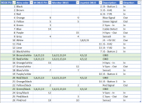
tl;dr: an Excel sheet which lets you sort by which pin to reference (HD26 side, or each of the DB15 ends) to assist in assembling - see here: https://1drv.ms/x/s!AohUnCWEgUwAhYBLhNsTRlNsGaYNXQ
Buy this cable: https://www.arrow.com/en/products/cs-dsdhd26mm0-005/amphenol (the colors inside this cable are what the colors in the spreadsheet refer to)
Buy these connectors: https://www.arrow.com/en/products/da15p064txlf/amphenol-fci (male DB15s - one for monitor input from Mac's video-out port), and https://www.arrow.com/en/products/da15s064tlf/amphenol-fci (female DB15s - one for joystick on PDS cable, one for monitor output)
Buy these shrouds to make it pretty: https://www.arrow.com/en/products/86303638blf/amphenol-fci
Wire it per the spreadsheet, and you're good to go.
So, back story. Seems that every time I run into a PC Compatibility Card, it is _always_ missing its cable, rendering it useless. They've always caught my interest, as a full PC-on-a-card, an odd piece of pre-virtualization history. But I've never been able to actually use one, because I've never had the cable.
I acquired a Centris 610 with a 486 DOS card and just barely enough RAM for everything to run smoothly (4mb onboard+8mb extra; 8mb on DOS card). But again... no cable.
I found the HD26 cable easily enough, and eventually the pinout (thanks to an old Apple doc that was pasted around the internet). This reference in particular: http://www.oliver-schubert.com/DOScard/MonCables.html
But one cable was never documented -- the joystick-port version used, apparently, on the early PDS version of the card ("Houdini", I've seen it called). Conflicting reports between the cable I have in my hand, and the article above, have this old joystick cable as either 590-0905 (the one I have and copied), and 590-2104 (in the page above). Hopefully they're the same.
I first tried making the cable in the page above, which I now know is one for the later PCI cards, but it did nothing - absolutely nothing. I'd later find that the pinout was completely different between these two versions, even though the connector is the same.
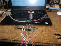
I found someone that'd loan me their PDS cable, so I can map it out and document it. Then, I cloned the cable (with the parts at the top, here), and the cloned cable works perfectly.
So, here now, is the mapping of the PDS version of the cable. Above, you can download the spreadsheet and sort it interactively, which is a major aid in assembly.

In building my copy of the cable, I joined all the grounds together (14, 15, 20, 23) from the 24-pin, to a single thick 16-gauge strand of wire, then soldered 12 wires of unique (in-set, not among grounds) colors to the other end, so I had 12 ground wires to go between the 3 ports (split as 4, 5, and 3 as above). For each of the R, G, B, and S1, S2, S3 wires, I just cut and spliced a second same-colored wire so, for example, orange became two oranges, so I can split them between the input and output ports. I had spare wire of each color due to trimming out a length of the (oversized) starting HD26 M-M cable.

Somewhere between the 4th and the 6th splice-pair, I started to wonder if this would be more manufacturable as a PCB instead of a cable.

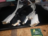
The clone, and the original.
For completeness, the already-well-documented PCI card's pinout is also in the spreadsheet (in the first tab). I did that so I could sort the pins and build the first "clone" I did. It's pretty easy to build these cables when each pin has a unique color and you can just look up a pin and find a certain color wire to put there.

Buy this cable: https://www.arrow.com/en/products/cs-dsdhd26mm0-005/amphenol (the colors inside this cable are what the colors in the spreadsheet refer to)
Buy these connectors: https://www.arrow.com/en/products/da15p064txlf/amphenol-fci (male DB15s - one for monitor input from Mac's video-out port), and https://www.arrow.com/en/products/da15s064tlf/amphenol-fci (female DB15s - one for joystick on PDS cable, one for monitor output)
Buy these shrouds to make it pretty: https://www.arrow.com/en/products/86303638blf/amphenol-fci
Wire it per the spreadsheet, and you're good to go.
So, back story. Seems that every time I run into a PC Compatibility Card, it is _always_ missing its cable, rendering it useless. They've always caught my interest, as a full PC-on-a-card, an odd piece of pre-virtualization history. But I've never been able to actually use one, because I've never had the cable.
I acquired a Centris 610 with a 486 DOS card and just barely enough RAM for everything to run smoothly (4mb onboard+8mb extra; 8mb on DOS card). But again... no cable.
I found the HD26 cable easily enough, and eventually the pinout (thanks to an old Apple doc that was pasted around the internet). This reference in particular: http://www.oliver-schubert.com/DOScard/MonCables.html
But one cable was never documented -- the joystick-port version used, apparently, on the early PDS version of the card ("Houdini", I've seen it called). Conflicting reports between the cable I have in my hand, and the article above, have this old joystick cable as either 590-0905 (the one I have and copied), and 590-2104 (in the page above). Hopefully they're the same.
I first tried making the cable in the page above, which I now know is one for the later PCI cards, but it did nothing - absolutely nothing. I'd later find that the pinout was completely different between these two versions, even though the connector is the same.
I found someone that'd loan me their PDS cable, so I can map it out and document it. Then, I cloned the cable (with the parts at the top, here), and the cloned cable works perfectly.
So, here now, is the mapping of the PDS version of the cable. Above, you can download the spreadsheet and sort it interactively, which is a major aid in assembly.

In building my copy of the cable, I joined all the grounds together (14, 15, 20, 23) from the 24-pin, to a single thick 16-gauge strand of wire, then soldered 12 wires of unique (in-set, not among grounds) colors to the other end, so I had 12 ground wires to go between the 3 ports (split as 4, 5, and 3 as above). For each of the R, G, B, and S1, S2, S3 wires, I just cut and spliced a second same-colored wire so, for example, orange became two oranges, so I can split them between the input and output ports. I had spare wire of each color due to trimming out a length of the (oversized) starting HD26 M-M cable.

Somewhere between the 4th and the 6th splice-pair, I started to wonder if this would be more manufacturable as a PCB instead of a cable.

The clone, and the original.
For completeness, the already-well-documented PCI card's pinout is also in the spreadsheet (in the first tab). I did that so I could sort the pins and build the first "clone" I did. It's pretty easy to build these cables when each pin has a unique color and you can just look up a pin and find a certain color wire to put there.

Last edited by a moderator:
