• Updated 2023-07-12: Hello, Guest! Welcome back, and be sure to check out this follow-up post about our outage a week or so ago.

Crazy Thoughts/Minor Hack: SWIM Chip Form Factor change - PLCC to DIP adapter! (?)

gogopuffs

Well-known member
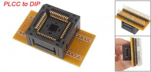
ux_a11060800ux0146_ux_c.jpg

See that adapter? Think about it as a little bit of inspiration.

So, the SWIM chip as we all know is an upgrade to earlier Macintosh SE machines that were equipped with 800k drives and was once an upgrade option for users who want to read and write 1.44MB floppy drives.

I'm now an owner of a battery-acid-victim SE/30 motherboard and was wondering about what could be used as a donor for other systems.  I am also in possession of an 800k Macintosh SE overseas and was just fantasizing about using the SWIM chip and SuperDrive from the SE/30 in the SE.

First problem:  form factor. The IWM and SWIM chip in the Macintosh SE is the 28 pin DIP package. Yeah, good enough. Too bad that the SE/30 SWIM form factor comes in a 44-pin PLCC form factor. (square package with pins on all sides vs. rectangle package with pins only length-wise)

So, looking a little deeper at the documentation referenced below, it seems they are work-alikes, they just need to be wired up properly.

And possibly it may mean that I need to do a bit of board design to get the right pinouts. This is new territory for me, but nothing's impossible, right?

So then the living Mac SE gets the SWIM chip in the bespoke cradle in a DIP package, the SuperDrive from the donated SE/30, and a whole new era of parts salvage possibilities comes about. This feels easier than, say, trying to emulate the behavior of a SWIM chip in a programmable package (using a Teensy or similar that's more powerful than the Mac SE itself.. ha!) 

Assuming the board pinouts were routed appropriately and the thing actually works, I'd imagine this would be useful for people doing resto-mods and retro-upgrades to their Macintosh SE machines.  Donor boards for SWIM chips wouldn't be limited to just SE/30's, they could come from Classic logic boards, IIci boards, etc. 

References:

http://mirror.informatimago.com/next/developer.apple.com/technotes/hw/pdf/hw_14.pdf Apple Technical Note HW14

<a data-ipb="nomediaparse" data-cke-saved-href="http://ftp.netbsd.org/pub/NetBSD/misc/wrstuden/Apple_PDFs/SWIM%20Chip%20User"href="http://ftp.netbsd.org/pub/NetBSD/misc/wrstuden/Apple_PDFs/SWIM%20Chip%20User" s%20ref.pdf"="">http://ftp.netbsd.org/pub/NetBSD/misc/wrstuden/Apple_PDFs/SWIM%20Chip%20User's%20Ref.pdf Apple SWIM Chip Reference Guide

http://www.ccadams.org/se/MacSEservice.pdf Mac SE Service Guide

Mods - feel free to move this message into a different forum if it's not appropriate - hardware hacks? I dunno. 

 
Last edited by a moderator:

gogopuffs

Well-known member
Whoa, well done!  Was thinking "hey! My work is done!" but I think you were going the other way around and also using the smaller form factor PLCC pinout rather than the SE/30 44-pin PLCC to the SE 28 pinster.

Thanks for confirming my theory of swap-eration!

 
Last edited by a moderator:

techknight

Well-known member
But....

To use the FDHD SWIM on the SE, you need to swap the ROMs as well as it has the updated .Sony driver for handling HD disks. 


gogopuffs

Well-known member
Ahh, yes.  But that being straightforward, couldn't replacement ROMs simply be programmed with an ordinary ROM programmer?

 
Last edited by a moderator:

techknight

Well-known member
As long as the pinout is the same. I think you can use EPROMs in there. But dont quote me on that. 


Scott Squires

Well-known member
The SE ROMs are the same as M27C512, except that pin 22 is an extra address line, making them 128K instead of 64K. Since pin 22 is normally the program voltage pin on the M27C512, I don't think you can find a 28-pin direct replacement. But you could probably make an adapter to hold a 32-pin EPROM.


8bitbubsy

Well-known member
Sorry for bumping a really old thread, but have anyone actually tried this? I have a PLCC44 SWIM from a Macintosh IIsi, and I would like to try and hack it onto a DIP28 socket, for use in a Macintosh SE. Maybe we could design a simple adapter board, with a DIP28 layout and a PLCC44 socket?
 

8bitbubsy

Well-known member
I made a conversion diagram:

Code:
PLCC44            DIP28
  35       --->     1
  36       --->     2
  37       --->     3
  40       --->     4
  41       --->     5
  42       --->     6
  43       --->     7
   2       --->     8
   3       --->     9
   4       --->    10
   5       --->    11
   8       --->    12
   9       --->    13
1,12,23,34 --->    14 (ground, use wider trace/wire)
  13       --->    15
  14       --->    16
  15       --->    17
  18       --->    18
  19       --->    19
  20       --->    20
  21       --->    21
  24       --->    22
  25       --->    23
  26       --->    24
  27       --->    25
  22       --->    26 (vcc)
  31       --->    27
  32       --->    28

I'll order some sockets and stuff and experiment with this. What I want to do, is to design a single PCB that plugs in to the ROM HI, ROM LO and IWM sockets. It will take a 44-pin SWIM and two 27C010 (or 27C1001) EPROM chips so that you get one solution instead of having to make adapters for both the ROM chips and the new SWIM. However, I have never designed a PCB before, so don't expect this to go well... Will also have to design it in a way where it would fit with an accelerator card installed.
 
Last edited:

8bitbubsy

Well-known member
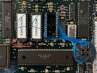
So yeah, using a PLCC44 SWIM from a Macintosh IIsi is confirmed to work on a Macintosh SE with FDHD ROMs.
I initially thought all my work was wasted as I got garbage on boot, but it turned out the chip enable (/G) wire had broke off on the high ROM as you can see in the picture, so I had to solder it back on.

I'm not going to design a PCB for this after all, since the original sockets can't handle thick pins. I replaced the three sockets myself with machine tooled ones.
 

zigzagjoe

Well-known member
So yeah, using a PLCC44 SWIM from a Macintosh IIsi is confirmed to work on a Macintosh SE with FDHD ROMs.
I initially thought all my work was wasted as I got garbage on boot, but it turned out the chip enable (/G) wire had broke off on the high ROM as you can see in the picture, so I had to solder it back on.

I'm not going to design a PCB for this after all, since the original sockets can't handle thick pins. I replaced the three sockets myself with machine tooled ones.
Nice work! You can get headers with machine pins (round) that should work with the original sockets. I've ordered these before.
 

8bitbubsy

Well-known member
I see, but I still don't want to design this PCB after all, since I've never designed a PCB before and it's a lot of work.
At least I have verified that the PLCC44 SWIM variant will work when rewired to DIP28, so that's something.
 

8bitbubsy

Well-known member
@max1zzz - maybe your PCB prowess could help here?
If there's a market for these things, but I kinda doubt it. You need to source a SWIM chip in the first place, and that's not going to be easy.
Maybe it would be better to try and replicate the SWIM chip with a microcontroller instead (or an FPGA if needed, but that would be costly).
 
Top