-
Updated 2023-07-12: Hello, Guest! Welcome back, and be sure to check out this follow-up post about our outage a week or so ago.
You are using an out of date browser. It may not display this or other websites correctly.
You should upgrade or use an alternative browser.
You should upgrade or use an alternative browser.
Compact Mac Power Meter Tool. :-)
- Thread starter uniserver
- Start date
techknight
Well-known member
Well I am not a sports fanatic, I dont watch it at all so i dunno. lol.
bigmessowires
Well-known member
Let me know if you get that converter board made. I just submitted some identically-sized boards to OSHPark: $6 shipped for three copies. Hard to beat that!
techknight
Well-known member
Hey uni, with the mac plus you can add the termination diode in its little spot on the PCB too 
techknight
Well-known member
Yup, and the PCB at least the versions I saw, has a spot for the diode but its un-populated. Once you populate a diode in there, boom you have termination power.
techknight
Well-known member
Good question... Its also a 1985 board, so it could be a later version but they didnt populate the diode. I dont know why.
techknight
Well-known member
oooo Now we are talking!!
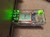
And actually, with a slight redesign on the floppy emulator, and using the internal ADC reference of the AVR and some resistor-dividers, technically the atmel can monitor voltage supply and report it to the LCD.
And actually, with a slight redesign on the floppy emulator, and using the internal ADC reference of the AVR and some resistor-dividers, technically the atmel can monitor voltage supply and report it to the LCD.
Last edited by a moderator:
bigmessowires
Well-known member
Mmm… glowy green electronics. [^]
bigmessowires
Well-known member
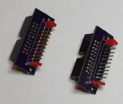
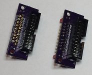
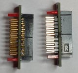
I got back the boards for the two DB-19 substitutes, and put them together today. Both versions use pins sticking out of a PCB, and a couple of rectangular LEDs as mechanical guides. Then there's an IDC-20 connector on the other side of the PCB, where you can attach a cable.
Version A is based on a modification of Uniserver's idea, and uses 0.1" header split up into a few unevenly spaced sections. The DB-19 pin spacing is close to 0.1", but not exact, so the header pins end up getting kind of bent. That's not great, but this version is pretty cheap and easy to build.
Version B uses 19 individual D-SUB crimp pins. The spacing is perfect to match the DB-19 female port. But it's kind of a bitch to build this version, since you have to stuff 19 pins one at a time, and use a female port as a jig, and then cut off the crimp section of each pin when you're done. And the crimp pins are a lot more expensive than regular 0.1 inch male header.
Both versions seems to work just fine. I ran a Floppy Emu through some exercises on a couple of different Macs, with both versions of this board. There were no problems, and the connector stayed firmly in the socket.
I think I'm going to make another revision, that's a tweak of the version A shown here. But instead of splitting up the 0.1 inch header as 5-5 and 5-4, I'll split it as 3-4-3 and 3-3-3. That will be slightly more work to assemble, but will result in less pin bending.
Photos below, version A on right, version B on left:


Similar threads
- Replies
- 4
- Views
- 482
- Replies
- 0
- Views
- 214

