• Updated 2023-07-12: Hello, Guest! Welcome back, and be sure to check out this follow-up post about our outage a week or so ago.

Compact Mac Power Meter Tool. :-)

bigmessowires

Well-known member
Thanks for trying it out! So my math says that's 18 ohms, which should draw 277 mA from the supply assuming everything else is zero resistance. You're seeing a drop to 4.1 - 4.2V? That's pretty significant, although 277 mA is a bigger load then you're likely to see in reality (I think Floppy Emu is like 150 mA). Does it change if you wiggle the connector around, to get more contact between the corner of that square pin and the round socket? 


uniserver

Well-known member
let me do it one more time… i want to make sure i am not a decimal place off. 

 
Last edited by a moderator:

uniserver

Well-known member
ok i did it again 

with out resistors…  5.0

with resistor 4.9

so pretty sure that is .09 of a drop… sorry about the confusion.

the multimeter was reading 4.99

LOL so i just  did the same test with the last extra db19 connector and i got

4.80  , granted the connector pins might have flux on them.. etc..

i am going to do a video.

Stand by…  

the header holds in there nice.. its snug…  i wiggle it… its solid across all 3 meters.. no jittery numbers or anything.

 
Last edited by a moderator:

bigmessowires

Well-known member
I've been experimenting with your substitute DB19, built from 9 1/2 pairs of angled 2-pin 0.1" header. I think I have a slightly improved solution: 3 straight 5-pin 0.1" headers and 1 straight 4-pin 0.1" header. The spacing between holes on the DB19 isn't 0.1", so it's not quite the right fit, and a 9- or 10-pin header strip won't go in. But if you use 4- or 5-pin strips, the pins have enough bend to them that they'll fit snugly. 


bigmessowires

Well-known member
One drawback is that without the surrounding flange (is that the right word?), it's possible to insert the connector so that the whole thing is offset 1 position left or right. That would be instant death for any sensitive electronics that suddenly got +12V. I wonder if there's a way to build enough of a poor-man's flange to prevent that from happening.


techknight

Well-known member
I wonder if you could design "the shield" as plastic in a printed/molded case? Because then you can solder the pins in place on the PCB, and when the housing is snapped together, everything aligns on the DB19. 


bigmessowires

Well-known member
A plastic shield would be great, but I don't know where or how you'd get those made cheaply and in small quantities. 3D printing is cool for novelties, but probably too slow and expensive for something like this. Any suggestions for a source?

I was thinking maybe there's some common electronic parts that I could throw on there, to function like a shield, even if they didn't do anything electrically. Randomly searching Digikey for parts that are tall, thin, and cheap. :) Some kind of rail or tab or something maybe...


uniserver

Well-known member
did you call up foxconn in china and ask them to make you some db19 connectors?

maybe have em make you like up like 5000 or something,  then you can be the world master distributor of them :)

they probably still have the Die's in a file cabinet somewhere.


bigmessowires

Well-known member
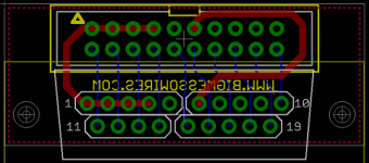
OK, I have a couple of little PCBs here that I think could work as a DB19 substitute. I decided to forget about the shield, and instead I added holes where the mounting screws normally go, so you can visually see from behind whether the connector is aligned properly. If somebody still messes it up, well, too bad.

The first one uses the footprint I posted above, relying on slight bending in four sections of standard 0.1 inch header. Then it's got a standard IDC-20 header above that, where you can plug in a cable. The whole thing has to be very tiny in order to fit the recessed area around the I/O ports on the Mac 128K and 512K.
db19-alt.png

The second one (not pictured) is basically the same as the first, except the holes are exactly on a standard D-SUB pitch of 2.77mm. Then you can put 19 individual D-SUB crimp pins in the holes, solder them, and cut off the crimp part of each pin. It would be more awkward and expensive to assemble, but would give a better fit and might be more reliable in the long-term than bendy square header pins. I'm going to talk to the assembly guys I use and ask how much of a pain this would be to assemble.

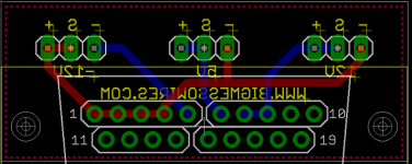
I also used the first footprint to make you a PCB for your power meter. This is basically the thing you asked me about over email that I said I wasn't going to do. :) It's got minus, sense, and plus broken out for each power rail. The lines are swapped for the -12V supply. You can send these Gerbers to Seeed or somebody if you want to get boards made.
power-meter.png

power-meter-render.png

power-meter-gerbers.zip

power-meter-eagle-files.zip


Attachments

  • power-meter-gerbers.zip
    26.3 KB · Views: 83
  • power-meter-eagle-files.zip
    9.8 KB · Views: 75

techknight

Well-known member
your pin spacing for the DB19. I am looking at the pictures, and the pin spacing is wider in the middle? 

 
Last edited by a moderator:

bigmessowires

Well-known member
Yeah, that's intentional. The spacing in between the sets of 0.1" header is due to the difference in the grid spacings between the header and the DB-19 female port. The middle pin in each strip of 5 is dead-center on the D-SUB 2.77 mm grid, then its neighbors are slightly off. Then the pattern repeats in the next strip of 5, so there's a little gap. If all 9 or 10 pins in the same row of the PCB were evenly spaced, then header won't fit into the D-SUB port.


bigmessowires

Well-known member
Yeah, this was the school fight song:

secant! cosine! tangent! sine!

3.14159!

integral, radical mu d-v

slipstick, slide rule, MIT!

We didn't win a lot of football games.

 
Top