croissantking
Well-known member
Just under the Firelink chip in your photo there are a whole bunch of them.
Fast blow I'd say.Do I want a slow blow or fast blow fuse at F1?
Any better: ?Just under the Firelink chip in your photo there are a whole bunch of them.
Yes; cheers!Any better: ?
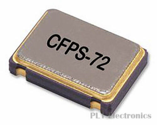
What are the dimensions? Would a 0705 part fit? (7mm x 5mm)I'm trying to work out what oscillator to use, I know for certain it's a 48Mhz part and probably 5V at that
Just looked at this. Yes, it's 7x5mm.What are the dimensions? Would a 0705 part fit? (7mm x 5mm)
Just looked at this. Yes, it's 7x5mm.
Thanks, that's really helpful.I think that is what you are looking for.
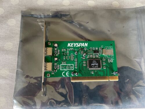
Sorry for the delay, here is my best shot I think. Very hard to do without a real macro lens.@mg.man @zefrenchtoon What are the resistor values used, I can't quite see?

A pull-up resistor is connected between a signal and the power rail (say +5V), so that the signal is “pulled up” to a logic 1 if it’s not driven by an active driver, while a pull-down resistor is connected between a signal and Ground so that the signal is “pulled down” to a logic 0 when undriven (this assumes positive logic, where the higher voltage is a 1 and 0V/GND is a 0).Also, could someone please tell me the difference between a ‘pull-up’ and ‘pull-down’ resistor
Thanks!A pull-up resistor is connected between a signal and the power rail (say +5V), so that the signal is “pulled up” to a logic 1 if it’s not driven by an active driver, while a pull-down resistor is connected between a signal and Ground so that the signal is “pulled down” to a logic 0 when undriven (this assumes positive logic, where the higher voltage is a 1 and 0V/GND is a 0).
Typical values for pull resistors are 1k - 100k Ohms, though others are possible. A lower resistance is a “stronger” pull, in that the driver must source or sink more current in order to overcome the “pull”, while a high resistance is a “weaker” pull, as less current is required.
You shouldn't need to?Thanks!
I think I am going to have to blindly experiment with capacitor and resistor values.
How do you mean?You shouldn't need to?