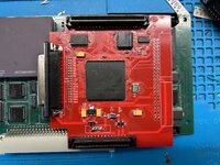
my03 Posted November 13, 2020 Report Share Posted November 13, 2020 Hi, My SE/30 started to show the "simasimac" lines last week. It displayed them for 6-8 minutes after which it gave the beep and started up normally. Reading about this told me that it was time for a re-cap. so i recapped my SE/30 today after receiving a recap-kit yesterday. It was somewhat tedious (i'm no fan of surface mount) but went mostly ok. "Mostly" meaning everything EXCEPT for the tiny 1µf - 50V where i accidentally managed to lift one of the solder pads. The machine now starts up immediately and i can't detect any issues despite this tiny cap not being connected. Or what am i missing here? What would be the potential problem of running without this in place? Quote Link to post Share on other sites
PotShotScott Posted November 13, 2020 Report Share Posted November 13, 2020 (edited) I think you're referring to C6 near UB10 and UB11. That capacitor is small and is adjacent to UB11. In the schematic it is labeled SND-R-A/D which means it could be a filter of some sort for the A to D converter for the Right sound channel. You likely have mono audio on this unit and can't tell because you're using the internal speaker. I could be wrong about this but as you note it's not a "deal breaker" for the unit. If you wanted to graft in a trace fix simply determine which side is good and solder to the "bad" side. So - if ground side is good on C6 then solder a small wire from the other side to pin 7 on UB11. Edit: I assumed that the triangle goes to a common (Ground) but upon further review I'm not quite sure where that goes. Maybe someone else knows what those triangles mean? Edited November 13, 2020 by PotShotScott Quote Link to post Share on other sites
Elfen Posted November 13, 2020 Report Share Posted November 13, 2020 1 hour ago, PotShotScott said: Edit: I assumed that the triangle goes to a common (Ground) but upon further review I'm not quite sure where that goes. Maybe someone else knows what those triangles mean? The triangle is ground, Quote Link to post Share on other sites
Elfen Posted November 13, 2020 Report Share Posted November 13, 2020 Lovely schematics, BTW, PotShotScott... Now, unless I'm misreading this, U10 and U11 are the sound amplifier chips on the board, U10 being the Left Channel and U11 being the Right Channel. C6 is the cap for U11's Sound A/D Channel, but is it input or output? From the looks of it, it being an A/D (Analog/Digital) channel, to me it looks like Input. So guessing, Sound Input is being taken to ground. this makes sense as the SE\30 is one of those early Mac with no Sound Input capability. But this is all a guess. (I also notice that the chips use 12V and not 5V). You can test it by plugging in a pair of headphones to the sound jack in the back of the Mac and see if you can hear both channels. If you get sound on both channels, then my guess was right. Quote Link to post Share on other sites
PotShotScott Posted November 14, 2020 Report Share Posted November 14, 2020 (edited) Thanks for the confirmation on the triangles Elfen. Going with your theory maybe they took that pin to ground to try and increase the SNR on that sound chip for the output? Problem is I don't see any resistors or inductors in the circuit that would make a filter. Also - the schematics are here: https://museo.freaknet.org/gallery/apple/stuff/mac/andreas.kann/schemat.html What I like about these schematics is they can be zoomed unlike the GIFs floating around the Interwebs with the rest of the cat videos Edited November 14, 2020 by PotShotScott Quote Link to post Share on other sites
my03 Posted November 14, 2020 Author Report Share Posted November 14, 2020 Hi PotShotScott and Elfen, I'm extremely glad to hear that it "only" affects the sound of the machine. Knowing this, i can always use a bodge-wire to connect them later on. Thanks also for the superb schematics. Quote Link to post Share on other sites
cheesestraws Posted November 14, 2020 Report Share Posted November 14, 2020 12 hours ago, PotShotScott said: I assumed that the triangle goes to a common (Ground) but upon further review I'm not quite sure where that goes 10 hours ago, Elfen said: The triangle is ground, To clarify very slightly; the triangle is the ground for the digital circuit. The leggy thing that the speaker jack is connected to is, I believe, chassis ground. Quote Link to post Share on other sites
PotShotScott Posted November 15, 2020 Report Share Posted November 15, 2020 I spent 5 years as an aviation electronics technician in the US Navy. They pounded into us the idea that ground is ground is ground (repeat several times). I'm feeling lazy right now (to verify with VOM) but wouldn't those ground pins for the digital circuit be on the same plane as the analog ground? Quote Link to post Share on other sites
cheesestraws Posted November 15, 2020 Report Share Posted November 15, 2020 I am on dangerous ground here (hah) because I don't really know what I'm talking about, but: they are joined, but they're not the same plane. I believe the reason for this is to try to prevent the analogue parts of the system being mucked about with by the noise generated by the digital parts. You segregate the two on the board then join them up at the PSU or something like that. Working out exactly why which device is connected to what and how that prevention is done is well above my level of competence, so I'm not even going to speculate . Quote Link to post Share on other sites
karrots Posted November 22, 2020 Report Share Posted November 22, 2020 https://www.arrow.com/en/research-and-events/articles/principles-of-grounding-for-mixed-signal-designs#:~:text=Analog Ground vs.,problems in sensitive analog circuits. Quote Link to post Share on other sites
cheesestraws Posted November 22, 2020 Report Share Posted November 22, 2020 6 hours ago, karrots said: https://www.arrow.com/en/research-and-events/articles/principles-of-grounding-for-mixed-signal-designs#:~:text=Analog Ground vs.,problems in sensitive analog circuits. That was really interesting, thankyou for posting that. It's cleared up a few things I found confusing. Quote Link to post Share on other sites
Oberlehrer Posted November 22, 2020 Report Share Posted November 22, 2020 A couple of interesting things in this circuit: AGND and CMMGND pins are both connected to digital ground. Usually AGND signifies analog ground. For some reason both sides also have different capacitor values for identical circuit positions: C6 is 1uF while C24 is only 0.1uF. Also, the numbering for C24 is somewhat out of place; based on the rest of the circuit I would expect this to be C7. Any ideas for the reasoning behind this? Quote Link to post Share on other sites
Recommended Posts
Join the conversation
You can post now and register later. If you have an account, sign in now to post with your account.