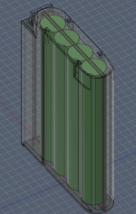
quorten Posted December 8, 2020 Report Share Posted December 8, 2020 @Kai Robinson Possibly... one thing that makes me think about is setting up some sort of independent "hardware test fixture" like I've designed (but haven't yet tested) for the RTC chip, but for the BBU I'm still tweaking the logic and setting up the simulation test. Things have been exciting for me work-wise, I started a new job last week. Quote Link to post Share on other sites
demik Posted December 11, 2020 Report Share Posted December 11, 2020 (edited) On 11/4/2020 at 10:34 PM, Kai Robinson said: However, thanks to Rob Taylor, the man responsible for getting me into the reverse engineering in the first place, I now have a new toy to play with! Finally a proper PAL dumper! Will get a ZIF socket but i have everything else I need - anyone else want one? I'm reversing a MacSNAP SCSI ATM and would love one of these. Are they still avaible ? Edited December 11, 2020 by demik Quote Link to post Share on other sites
SlickClick Posted December 12, 2020 Report Share Posted December 12, 2020 What Speed are you running the system bus at..? I noticed the CPU you are using is the later version which can run at high speeds... The system is designed at 7-8Mhz bus speed... When you up the System Bus Speed it gets wonky with the Analog Video Circuity; if you're running a high Clock Speed that may be part of your issue as well... The Higher Voltage of 7.5v might only effect the smaller 3.3v circuit as that would be at the top of the tolerance levels (ie Double Voltage)... Check that your RAM is still good... Quote Link to post Share on other sites
quorten Posted December 12, 2020 Report Share Posted December 12, 2020 Hello @SlickClick, welcome! In this case the master clock should be ~16MHz and the BBU divides that down to the ~8MHz CPU clock. Have you actually run a Macintosh SE with a higher speed master clock? I would have suspected that higher master clock speeds wouldn't work at all without a BBU mod, but if they do in fact work by simply overdriving all the generated clock frequencies, that would be good to know for the BBU replica design. The Macintosh SE MLB doesn't have a 3.3V power circuit to my knowledge, it should all be 5V chips on there, assuming that vintage RAM is used. Quote Link to post Share on other sites
Kai Robinson Posted December 13, 2020 Author Report Share Posted December 13, 2020 @SlickClick 7.83Mhz is the Bus speed in the system. The CPU is an L10 - mostly because it's a nice, gold top ceramic CPU, no other reason Quote Link to post Share on other sites
anthon Posted December 14, 2020 Report Share Posted December 14, 2020 OK, I've been out of the 68k loop for a couple of years. Now look what is going on! Very nice! The Mac SE overall is the most reliable of the compact Macs. (Perhaps even most reliable of any Mac.) Through-hole parts, no leaky caps, the batteries don't often explode (mostly I have seen the Varta and Tadiran batteries in SEs, nigh a Maxwell to be found). The real Mac that needs replacement PCBs is the SE/30. I alone have at least 4 of those with trace rot beyond salvage. That one's more complicated though, so it makes a lot of sense to start with the SE. I need to learn Verilog so I can help with the custom chip side of things. I've been saying that for 3 years... Quote Link to post Share on other sites
rplacd Posted December 14, 2020 Report Share Posted December 14, 2020 (edited) 44 minutes ago, anthon said: I need to learn Verilog so I can help with the custom chip side of things. I've been saying that for 3 years... Same! This thread has inspired me to take a good crack at learning digital design. As an early Christmas gift I bought myself an FPGA trainer board and a textbook. Edited December 14, 2020 by rplacd Quote Link to post Share on other sites
quorten Posted December 15, 2020 Report Share Posted December 15, 2020 On 12/13/2020 at 6:43 PM, anthon said: I need to learn Verilog so I can help with the custom chip side of things. I've been saying that for 3 years... What I've been thinking to myself about my knowledge of Verilog... I needed a few more classes to fill up my computer science degree electives and the relevant classes seemed like something that wasn't too over-hyped or overly specialized. Probably not going to use it at my main job any time too soon but it sure is fun for side projects. Ha ha ha! Quote Link to post Share on other sites
Hiro256 Posted December 16, 2020 Report Share Posted December 16, 2020 On 6/28/2020 at 4:46 PM, Kai Robinson said: So - as the title explains, this is designed to save as many Mac SE's as possible. So many have died thanks to the stupid PRAM battery on the board, and with the SE being a 2-layer PCB with just through hole components, it's actually one of the easiest to save. So - how do you reproduce a PCB? First, get a Mac SE PCB - in my case a 'dead' board from eBay for €29 - thanks, random spanish man! Then, you get to work desoldering. Literally EVERYTHING. Not a single component must remain! However, 30 year old solder and my ZD-915 desoldering station caused a handful of through holes to just pull out of the board, or some traces would come up with it. I found that pre-heating the joint, with a little flux (AmTech RMA-223), would make the solder melt a lot cleaner when you use the ZD-915 desoldering gun. You must use a lot of heat, on these boards. For those joints that have been corroded, you must flood the area with flux, heat from both sides, then try and move the pin using a soldering iron (i find 420 degrees C suitable, with a standard flat tip) before trying to use the desoldering gun. Sometimes it won't always come out of the joint, in which case reflood with flux, and attack it with desolder braid. I use 2.0mm GootWick, which is fantastic stuff (thanks to Louis Rossmann for the recommendation). As part of this process, I made a list of the parts that you need to save, and the ones that you can ditch. Obviously, all the custom Apple ones are a must - the rest are either still available, or are available as new-old-stock or pulls. So - here's what you need to save: SIMM Sockets - IMPOSSIBLE TO GET - desoldering these needs HEAT as there are a lot of connections to the ground plane. Pre-heat the joints, maybe add a dab of proper Kester 63/37 eutectic LEADED solder (none of that RoHS crap), flood with flux. PDS Socket - Amphenol/AMP/AVX DIN-41612 3-row, 96-pin connector (Style-C) - Available new, but still worth reclaiming as sifting through the minute variations of parts is an arse... Inductors - probably easy enough to get new ones, but ehhh, they don't really break, and they fit fine. AM26LS30's - NLA, only available as NoS or Reclaimed AM26LS32's - Available new, but still worth reclaiming MC3488A - NLA, only available as NoS or Reclaimed RTC Chip - Custom Chip - maybe possible to clone using pin-compatible ATTiny85 ADB Chip - Apple branded PIC16CR54 - maybe possible to re-produce/clone GLU Chip - Apple branded PAL16L8 - maybe possible to re-produce/clone BBE Chip - Custom Chip NCR5830/AM58C30 SCSI Chip - NLA, only available as NoS or Reclaimed WIM/SWIM Floppy Chip - Custom Chip Hi & Lo ROM Chips - Toshiba TC531000CP MASK ROM's - Reclaim & reuse, but these are the same pinout as 27C512, but adds A16 in place of VPP pin - you can use 27C1001's on an adapter - doug brown made a similar setup with a built in ROM disk for the Mac Plus. 74LS245 - Available new, but still worth reclaiming - replace with CY74FCT245ATPC or CD74FCT245E 74F257 - Available new, but still worth reclaiming - replace with CD74ACT257E DB19 Connector - NLA, only available as NoS or Reclaimed. These are a bastard to get out cause the lugs are soldered. I found that pre-heating the joint first, filled with flux, then pressing hard into the pad with the desoldering gun, waiting til you see the solder go molten, you can often schlorp out the majority of the solder and then tidy up with wick afterwards. Passives - REPLACE ALL - use high tolerance metal film resistors & nichicon or panasonic electrolytics. Maybe try and save the PLCC Socket if you can. remove it cleanly - sometimes the pins pull out but they can be put back in if you're careful. Once you've saved all those parts, it's time to get scanning! 800 to 1200dpi on your scanner. If your scanner bed cant quite fit the whole thing on, scan one side, then rotate 180 degrees, scan, flip the image, then you can merge the images in photoshop. My scanner clips about 5mm off, so i use this method. There will be a part 2 to follow...but any questions so far? Oh I see, the SIMM connectors for memory still used in Japan :). You can find most of the parts on the list actually, but probably better to put everything into one FPGA. https://www.mouser.com/Connectors/Memory-Connectors/Memory-Socket-Connectors/SIMM-Connectors/_/N-axja3 Quote Link to post Share on other sites
quorten Posted December 17, 2020 Report Share Posted December 17, 2020 (edited) Welcome @Hiro256! 16 hours ago, Hiro256 said: You can find most of the parts on the list actually, but probably better to put everything into one FPGA. Psst! Fine, I digress, if you're looking for a single FPGA design, Steve Chamberlin had done that 9 years ago and dubbed it the Plus Two. To my knowledge no one has ever been interested in picking that project up to polish it off, probably because the license/copyright terms on Steve's code portion of it were never clearly stated. https://www.bigmessowires.com/plus-too/ EDIT: Latest update is in 2015, at least one contributor picked up on the project. License/copyright info also appears ambiguous on that project. https://www.bigmessowires.com/2015/10/22/plus-too-mac-replica-new-progress/ Edited December 17, 2020 by quorten Note newer update Quote Link to post Share on other sites
Kai Robinson Posted December 17, 2020 Author Report Share Posted December 17, 2020 23 hours ago, Hiro256 said: Oh I see, the SIMM connectors for memory still used in Japan :). You can find most of the parts on the list actually, but probably better to put everything into one FPGA. https://www.mouser.com/Connectors/Memory-Connectors/Memory-Socket-Connectors/SIMM-Connectors/_/N-axja3 Brand new from PE Connectors for less than $2, too Quote Link to post Share on other sites
bigmessowires Posted December 18, 2020 Report Share Posted December 18, 2020 23 hours ago, quorten said: if you're looking for a single FPGA design, Steve Chamberlin had done that 9 years ago and dubbed it the Plus Two. To my knowledge no one has ever been interested in picking that project up to polish it off, probably because the license/copyright terms on Steve's code portion of it were never clearly stated. The Plus Too core is "open source". If you need a specific license, let me know. FYI the core was integrated into the MIST FPGA computer in 2015, and also received some significant bug fixes and additions from Till Harbaum, like a model of the SCSI chip. https://github.com/mist-devel/mist-board/wiki Quote Link to post Share on other sites
maceffects Posted December 18, 2020 Report Share Posted December 18, 2020 1 hour ago, bigmessowires said: The Plus Too core is "open source". If you need a specific license, let me know. FYI the core was integrated into the MIST FPGA computer in 2015, and also received some significant bug fixes and additions from Till Harbaum, like a model of the SCSI chip. https://github.com/mist-devel/mist-board/wiki I can't believe I never realized this project existed and I have an unused MiSTr FPGA computer that I was gifted. I'll have have to look into this more. Very cool project. Of course, @Kai Robinson SE reproduction is also very cool! I'm so very glad to see so many great people do so many amazing projects. MacEffects approves : Quote Link to post Share on other sites
quorten Posted December 18, 2020 Report Share Posted December 18, 2020 Great to see you back around here @bigmessowires. It would be a good idea to pick a particular permissive license or public domain dedication for the parts of Plus Two that you authored. I personally would have more openly shared info about the project if the license was more clearly stated. Quote Link to post Share on other sites
Phazmatis Posted December 21, 2020 Report Share Posted December 21, 2020 I know this is about reproducing the board itself, but I thought it might be useful to have a schematic version of the SE board. Well... I didn't get that far, but I did label many IC pins in Kai's (latest?) board image: annotated_se_board_001.png (5434×5434) This really helped me understand how the 68k, TPI, GLU, and BBU are all connected together. My eventual plan is to create a "Mac SE" board using more commonly available components. For instance, the TPI could be recreated with two VIAs. And the RAM SIMMs could be replaced with a bunch of socketed RAM DIP chips (like the Commodore 64 used). Just a weird hack idea, pretty pointless. (since I'd still need the BBU and GLU from a real Mac SE) Quote Link to post Share on other sites
Kai Robinson Posted December 21, 2020 Author Report Share Posted December 21, 2020 What is the TPI, I explained, was an error - it really is just a 6522 VIA - the pinouts didn't make sense if it was a 6523 TPI. Also it would be uncharacteristic for apple to suddenly use that once, then go back to the 6522 for everything else. Read back a few pages - we've all but reverse engineered the Glu, @quortenis working on the BBU and I've just begun manufacturing SIMMs... Quote Link to post Share on other sites
asicsolutions Posted December 22, 2020 Report Share Posted December 22, 2020 Hi! I am hoping I might be able to help some in your reverse engineering/ re-implementation projects as well as get some help. I'm an FPGA designer with about 30 years of ASIC and FPGA experience. I've released my open source GPU: https://github.com/asicguy/gplgpu. I'm happy to provide my skills if you need any help re-implementing retro stuff in FPGAs. Currently, I'm working with @maceffects on re-implementing the xceed board for the SE/30. I've got a design complete that we'll manufacture at some point in the near future and it will be open source. I also do a lot of work on the MiSTer project and a thought came to see if it would be possible to implement the SE/30 in MiSTer to "virtually" test my xceed design. That's where I hit a brick wall as only a MACplus has been implemented. I see that @Kai Robinson has dumped the GLU. As I'm a bit of a newb as far as MACs go, is that the same design used in the SE/30 or is that a different chip? Are there other custom chips I need to concern myself with? I'm sorry if these questions are basic or I missed the answers in the thread. Quote Link to post Share on other sites
maceffects Posted December 22, 2020 Report Share Posted December 22, 2020 (edited) @asicsolutions welcome abroad the 68kmla team. @Kai Robinson has done some pretty incredible things with the SE design. He would probably know better than me if the GLU implementation is the same or similar. regarding the Micron Xceed @joethezombie, @Bolle, @Trash80toHP_Mini, @techknight are the resident experts in this area. We can start a thread here regarding that as well. Edited December 22, 2020 by maceffects Quote Link to post Share on other sites
Kai Robinson Posted December 22, 2020 Author Report Share Posted December 22, 2020 @asicsolutionsIt's a separate chip than anything else - it's the only PAL left on the logic board - the rest were consolidated into the BBU - a single 84-pin PLCC. The GLU chip on the SE only does a few things, i sent it off to Porchy @ Jammaarcade for reverse engineering after my first attempt in an EPROM programmer (using the 27C020 dump method), and i posted the .jed earlier on. The BBU will be the one to reverse engineer and @quorten was on his way - but all the help we can get at this point! I'd recommend probably a CPLD rather than FPGA though. I think the ADB chip is the only irritance at this point - its a PIC16CR54, and it seems impossible to read out the contents of the ROM. Microchip has a PDF on how to use the 16x54 with ADB though, so might be possible to implement from scratch. How much info would you need? Happy to furnish you with a full PCB layout in Sprint - so you can see what connects to what - same goes for anyone else at this point - i'm starting to hit a wall, need more beta testers with complete boards Quote Link to post Share on other sites
cheesestraws Posted December 22, 2020 Report Share Posted December 22, 2020 2 hours ago, Kai Robinson said: need more beta testers with complete boards I have been really remiss on posting updates on this but I have been making slow progress as my brain will let me... in theory I should be getting the last components I need from RS tonight, if I haven't forgotten anything! Quote Link to post Share on other sites
asicsolutions Posted December 22, 2020 Report Share Posted December 22, 2020 @Kai RobinsonI lump CPLD and FPGA kind of together as their is much overlap in parts. I tend to like Xilinx as they are my daily driver at work, but certainly, whatever does the job. Schematics would be helpful. I have a 16550a logic analyzer I could hook up to the BBU if I could find a good way to do it. Perhaps making an interposer board with some mictor connectors that I could interface too. I used to do a lot of capture when debugging my graphics FPGA on the PCI bus. it might be a bit of a slog, but maybe I could reverse engineer it this way. I have a MAC SE/30 already. Hopefully my old logic analyzer still works Quote Link to post Share on other sites
Kai Robinson Posted December 22, 2020 Author Report Share Posted December 22, 2020 (edited) 2 hours ago, asicsolutions said: @Kai RobinsonI lump CPLD and FPGA kind of together as their is much overlap in parts. I tend to like Xilinx as they are my daily driver at work, but certainly, whatever does the job. Schematics would be helpful. I have a 16550a logic analyzer I could hook up to the BBU if I could find a good way to do it. Perhaps making an interposer board with some mictor connectors that I could interface too. I used to do a lot of capture when debugging my graphics FPGA on the PCI bus. it might be a bit of a slog, but maybe I could reverse engineer it this way. I have a MAC SE/30 already. Hopefully my old logic analyzer still works Then you'll be wanting one of these! I designed a universal Through-Hole PLCC84 breakout - remove the original PLCC socket from the board, solder this board in place with standoff pins, then solder new socket to this board and voila - all pins accessible easily with a Logic Analyzer. Attached Gerbers if you want to get a set made. For the Mac SE, the schematics aren't really available, there's only a single page available and it's grainy as hell. I'll post the Sprint Layout in a minute - you can download a trial version that should allow you to use it for 30 days, but i recommend buying it - it's excellent software for the $49 it costs. Might be worth looking at the ATF15xx series CPLD's as they're native 5v parts and don't need level shifters added. A 1508 would probably be big enough for the BBU. gerbers.zip Edited December 22, 2020 by Kai Robinson spelling Quote Link to post Share on other sites
asicsolutions Posted December 22, 2020 Report Share Posted December 22, 2020 I'll need to find someone good at soldering I can't solder to save my life, but that looks like it would let me monitor what is going on, thanks. Quote Link to post Share on other sites
maceffects Posted December 22, 2020 Report Share Posted December 22, 2020 @asicsolutions if you give me a BoM or everything needed, and assuming there are no SMD, I can get one of these and solder it together and send it your way. Quote Link to post Share on other sites
Kai Robinson Posted December 22, 2020 Author Report Share Posted December 22, 2020 @maceffects It's all 100% through hole - uses standard PLCC sockets and 2.54mm pin headers. Quote Link to post Share on other sites
Recommended Posts
Join the conversation
You can post now and register later. If you have an account, sign in now to post with your account.