Troubleshooting Mac SE/30 Floppy Drive Functionality

joseph

6502
My primary goal is to have a working internal high density floppy drive "SuperDrive" on a Macintosh SE/30. I'd appreciate any thoughts about my situation.

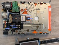
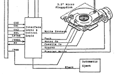
I received two 3.5" DSHD (FDHD) floppy drives, both Sony MP-F75W-01G floppy drives. One came out of the very SE/30 I'm working with. They were filthy and non-working and that prompted me to perform cleaning, re-greasing, and recapping (Console5 kits). It turned out that both floppy drives' original capacitor values measured mostly okay, and also the original worm mechanism gears were fine. I took some notes about the process.

Both drives do NOT read or initialize 3.5" DD or HD media in the SE/30 running System 6.0.8 or 7.5.5 with a 32-bit clean ROM (if the software environment makes any difference).

The Mac SE/30 I'm working with was formerly simasimac and was professionally repaired and tested by a service. The memory and ROM are new. It's running off of a plain Pico-based BlueSCSI. These are just notes, there's been no other issues with the computer.

The floppy disk media I'm working with fully functions (initializes, reads, and writes) in an external Apple 3.5 Drive (A9M0106) on the same Mac. The external drive will recognize and format my DD and HD disk media just fine. I thought this was only a DD drive, but HD seems to also work when on this controller. If I put these same disks in either Sony MP-F75W-01G, the computer prompts that it needs to initialize them. After running through that process it says that the disk is bad and ejects it. Putting that same disk back in the external drive shows it hasn't been touched and that there are still valid files and programs. There's truly no read or write happening on these Sony drives. I have tried two different floppy cables.

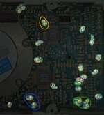
I read some posts on here about the UH7 SWIM chip. But if that component were bad, I think that the external drive also would not work? Adding a 2pF capacitor to the PCB as an experiment made no difference.

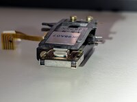
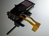
I took some videos of the Sony drives:
On eBay the external drives seem to be much cheaper than internal ones. Would parting out an external work as compatible substitute? I don't want to take apart the working external I already have.

I'll see about finding another Mac that takes FDHD to also try these in if that would help narrow things or not.

Would it help to find or buy a third auto inject drive to compare against these two?
 
Is the zero-track position on drive 1 properly aligned? Not exactly a trivial question, but I only ask because it was the issue for 3 in every 4 auto-injecting drives I've cleaned, and seems to be a common problem.
 
Is the zero-track position on drive 1 properly aligned? Not exactly a trivial question, but I only ask because it was the issue for 3 in every 4 auto-injecting drives I've cleaned, and seems to be a common problem.
It now certainly isn't because that I've fiddled with it. This looks daunting. Is there some other instrumentation I can use to help with this calibration? I notice the gate goes to 4.8V when the plastic passes through it.

The ZTA document linked on TinkerDifferent is asking for a mechanical skill that might be beyond my abilities. I'm supposed to tighten down a piece of plastic, with 0.5 mm of travel, that has a 0.035mm tolerance? Are there any ideas about making a jig or some assisting piece for this? I can't really see the dot I made.
Have you tried connecting the external drive directly to the internal cable for a test ?
I just tried your suggestion and it worked! 💾 (y) It was also another MP-F75W-01G inside of there. So I have three of these drives and one works; the external which is internal at the moment.
 
There is more head travel on drive 1 and it might not be clamping down enough. What's a good way to adjust that?

I made a video comparing the head travel on the drives. There's clearly a difference and drive 3 (the external) is tighter.

I've cotton swabbed the heads with IPA if that is sufficient to call them cleaned.

I hesitate to dissemble the working drive and swapping head parts around. I understand that would help with a process of elimination, but I'm not confident about placing it all back together working again. There's variable assembly like zero track sensor, head clamping, head alignment and I'm not sure yet what doing that correctly would look and feel like. I will try to find a second working drive so that I have some room for these experiments.
 
On eBay the external drives seem to be much cheaper than internal ones. Would parting out an external work as compatible substitute? I don't want to take apart the working external I already have.
It's the exact same drive in the external case, and straightforward to take apart (screws at bottom, lift off plastic housing, cable, remove shielding), there is your working internal test drive
 
I've placed Drive 2's heads into 1, but still have the zero track gate alignment to figure out. This combination is not working yet. But this has refreshed my practice with these mechanical things. Does anything wrong stand out in the photos with Drive 1's heads? I don't see a torn ribbon, or bad connector, or something burnt looking. What other things are there to look for?
 

Attachments

  • PXL_20260115_215324881.RAW-01.COVER.jpg
    PXL_20260115_215324881.RAW-01.COVER.jpg
    1.3 MB · Views: 5
  • PXL_20260115_215414297.RAW-01.COVER.jpg
    PXL_20260115_215414297.RAW-01.COVER.jpg
    787.3 KB · Views: 5
  • PXL_20260115_215425290.RAW-01.COVER.jpg
    PXL_20260115_215425290.RAW-01.COVER.jpg
    773.5 KB · Views: 5
For zero track alignment, I tried using some reference measurements taken from the working drive and then trying to dial that in on the other one. I got within 0.02mm, but still no luck.
 

Attachments

  • MP-F75W-01G ZTA references.jpg
    MP-F75W-01G ZTA references.jpg
    1 MB · Views: 6
Personally, I had to do my zero-track position with trial and error, and repeatedly plug the drive into a IIsi for testing. I did not have any kind of special equipment, so it was extremely tedious. The Larry Pina "Macintosh Upgrade & Secrets SE" book claims that being unable to fully initialize the disk, or initializing it with the wrong zero track (can only see your data/label from that specific drive) indicates getting closer, and not detecting a floppy at all generally indicates getting further away from the proper alignment. That was the book I was consulting for help, despite its age.

If you ever unscrewed the motor (stator) screws during cleaning, those are also a part of alignment, and they can be even more finnicky. If you left it alone, though, then it's probably fine.
 
Well, I searched and did find a 4th Sony MP-F75W-01G which works. So that concludes my thread's primary goal. I went through JDW's video a third time, redoing all of the lubrication. I didn't touch the zero track sensor on this one and the drive functions fine! It formatted those orange disks seen in the videos without any issues. This was the only model variant where I had to desolder the motor from the PCB in order to pop the gears out of the box. I'm going to reassemble my external drive.

Thank you Boctor, bibilit, and Byrd for the assistance and ideas.

It seems like there isn't yet the communal knowledge on using instrumentation to assist with the zero track alignment. I've got two very clean drives with new caps which need this performed. I have tried ~30 "different" positions for the screw and I could not get "Drive 1" to see a known good disk. I'm going to assume for now that between Drive 1 and 2's heads there is a working set. I'll test with Drive 4's heads as a last resort. I could spend hours trying to get that screw in the right position with Drive 4's heads? I'm just not understanding the marked shaft way of doing it. Unless I truly was doing that with bad heads before.

But I'd like to keep going in this thread about the ZTA because it seems like a way to "unbrick" a lot more drives out there.

It doesn't look like Greaseweazle or AppleSauce have any zero track aligning features. In search for information about ZTA, I found a Polish engineer's blog documenting the zeroing process on an IBM drive. The home page https://polprog.net/ looks cool if you're into Unix and ANSI art. Apple uses the same MFM 1.44MB on HD disks, so it should be the exact same process, no? The blog aligns it by rotating the head stepper motor. But my thought is that the sensor in the Apple drive could possibly be wiggled around while constantly spinning the disk on track 0. Measuring the A and B waveforms would hone in on getting a clear eye to help screw down the gate in place.

The forums here have an MP-F75W-01G schematic posted.

There's a specification document for the 400K drive out there. I'm not sure how compatible it is with the signals on a MP-F75W-x, but I can't find an 800K or FDHD spec doc.

A Raspberry Pi GPIO with a logic level shifter or something could drive these things. Comparing the blog with the Apple 400K drive:
  • Drive select/ENBL:0
  • Motor enableSEL:0, CA2:0; CA1:1, CA0:0, then LSTB high for 1us+, finally LSTB low
  • Direction select/DIRTN
    • Towards outside: /DIRTN: CA2:1, SEL:0, CA1:0, CA0:0, then LSTB high for 1us+, finally LSTB low
    • Towards center: /DIRTN: CA2:0, SEL:0, CA1:0, CA0:0, then LSTB high for 1us+, finally LSTB low
  • Head step/STEP falling edge: CA2:1, SEL:0, CA1:0, CA0:1, then LSTB high for 1us+, finally LSTB low
  • PWM / Drive Speed → Will have to figure this out. Do we know if the HD hole automatically sets this to 300rpm? The 400K drive says the host system does it while checking the tach pulses. Probably don't care since this isn't GCR. 390 - 605 RPM. <390 at 9.4% duty, >605 at 91% duty.
Using the Sony MP-F73W service manual for reference, it looks like XADJ is for radial alignment within a test fixture. Page 64 and 65 use similar chips to the Apple drive. There's no datasheets out there for the CXD1603Q, but the CXD1068Q likely has a similar pinout--unless the chip changes pins for an Apple controls version? But stuff like Motor On /MON, Step /STP, Direction /DIR, Index /IND are right on there if the pins are the same. Though it would be easier to solder to the TPs instead of QFP pins.

FG and U/D look like they have to do with measuring frequency and phase of the motor driver. Not sure what "H.C" would bridge.

I'm curious about other thoughts and ideas.
 

Attachments

  • Apple FDHD PCB Test Points.jpg
    Apple FDHD PCB Test Points.jpg
    985.2 KB · Views: 1
  • apple-400k-diagram.png
    apple-400k-diagram.png
    68.3 KB · Views: 1
  • apple-400k-signals.png
    apple-400k-signals.png
    105.6 KB · Views: 1
Back
Top