-
 Hello Guest! The forum software will be upgraded weekend of 06/26. See this announcement thread for more information.
You are using an out of date browser. It may not display this or other websites correctly.
You should upgrade or use an alternative browser.
You should upgrade or use an alternative browser.
Torn pad on Performa 475
- Thread starter D-50 Dude
- Start date


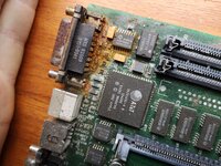
Some PSUs will make a ticking sound when not connected to a load, the fact that it ticks when connected to the motherboard could be the fault of either the motherboard or the PSU. Inspect the replaced caps on the motherboard to make absolutely sure that none of their solder joints are shorted to adjacent vias/tracks (probably a higher likelihood of that happening if the soldering iron wasn't always up to temp). Pictures of the board might be helpful if possible.
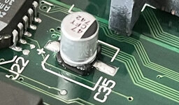
This was my first thought too. If you have a short on the logic board the PSU will click like that. Could definitely be something with the bodge work, also worth taking a look at the dark patches on those traces to the left of the power connector.Some PSUs will make a ticking sound when not connected to a load, the fact that it ticks when connected to the motherboard could be the fault of either the motherboard or the PSU. Inspect the replaced caps on the motherboard to make absolutely sure that none of their solder joints are shorted to adjacent vias/tracks (probably a higher likelihood of that happening if the soldering iron wasn't always up to temp). Pictures of the board might be helpful if possible.
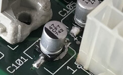
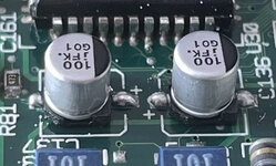
Looking at these photos myself, I didn’t realize just how bad it all looks. This is by far the worst job I’ve ever done with SMD.
Attachments
-
 E8781365-5892-4C00-8855-EA046E84050D.jpeg1 MB · Views: 17
 -
 C4CB6B3F-7F1D-405F-B045-10CE989EDF14.jpeg776.2 KB · Views: 12
 -
 4CB74E8E-8722-46C3-B958-148B6362A28C.jpeg911.7 KB · Views: 12
 -
 C2613B5E-B874-4EA8-9E13-A965150C5064.jpeg785.6 KB · Views: 12
 -
 92D32030-333D-439B-AC2E-A43A73CE9184.png9 MB · Views: 12
 -
 086AB09D-3511-4DB8-A14D-79B1DB8B2C42.jpeg1.1 MB · Views: 12
 -
 A9877D8C-23C7-4411-8CEA-4802C54B477F.jpeg1.1 MB · Views: 17

You could tidy that up fineLooking at these photos myself, I didn’t realize just how bad it all looks. This is by far the worst job I’ve ever done with SMD.
")
Do you have some flux? Dab some on, use some solder wick to remove the excess
If you do one side at a time the solder on the other side will helpfully keep everything in place while you faff.
Last edited:
Honestly, this project is becoming more trouble than it’s worth, and I may just sell the individual parts and put the money toward a 68040 accelerator card for the IIcx. On the plus side, at lest I can use the floppy drive in the IIcx. I didn’t pay too much for it so it’s not a huge loss. However, I may give the flux trick a tray in one last attempt . I really do appreciate all of the help and your patience.
. I really do appreciate all of the help and your patience.Don't give up, put it away and come back to it if you're frustrated. Sometimes I go away from a project to learn new skills or practiceHonestly, this project is becoming more trouble than it’s worth, and I may just sell the individual parts and put the money toward a 68040 accelerator card for the IIcx. On the plus side, at lest I can use the floppy drive in the IIcx. I didn’t pay too much for it so it’s not a huge loss. However, I may give the flux trick a tray in one last attempt
.I find working on things more fun than using them
the 475 I'm slowly repairing at the moment had fairly bad water damage, every time I make progress it is awesome When I'm done I'll have a great little, fast mac to play with.Do you have any friends with similar interests? It can be much more fun to bounce ideas off someone and talk about what to try next. It is frustrating until you make a big leap forward.
After ~ 2 calandar weeks of work on and off (not too many hours) on Friday I went from a completely dead, lifeless machine to booting with no sound, now I have sound but it crashes every now and then.
Attachments
That is a complex question. I understand that ceramic caps are nor completely correct for substitution with electrolytics, but... some people very strongly disagree with that.One more question. In the future, should I continue to use electrolytic caps for replacement or ceramic caps?
I use electrolytics or tantalum capacitors.
There is a chance (high) that it won't fit exactly - the older drives in the IIcx have a slightly different height slot to the ones with the black flap on the front.In the mean time, at least I can make use of its floppy drive in my IIcx.
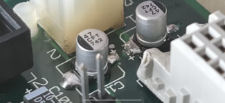
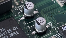
One thing I noticed in your fourth photo is that there appears to be some leftover solder paste that didn't reflow properly, would be a good idea to clean that up. The excess solder on some joints could've easily bridged to nearby tracks, solder wick + flux will help tremendously there as others have said. Definitely not the end of the world...
Solder paste works well when you have a stencil and squeegee to apply it, otherwise it can very quickly turn into a mess.
As far as straightforward replacements go, I'd be careful using ceramic parts in place of electrolytics. Of the many types of ceramics, most have properties wildly different from those of electrolytics (DC bias characteristic, temperature stability, ESR being some of the more important ones).
In most cases, your best bet would likely be a ceramic capacitor with an X5R/X7R dielectric, although it would be simpler to stick with electrolytics/tantalums. You might also check out aluminum polymer capacitors -- while they're a bit more expensive than electrolytics, they have the same dimensions and share many of the same properties.
Solder paste works well when you have a stencil and squeegee to apply it, otherwise it can very quickly turn into a mess.
In the future, should I continue to use electrolytic caps for replacement or ceramic caps?
As far as straightforward replacements go, I'd be careful using ceramic parts in place of electrolytics. Of the many types of ceramics, most have properties wildly different from those of electrolytics (DC bias characteristic, temperature stability, ESR being some of the more important ones).
In most cases, your best bet would likely be a ceramic capacitor with an X5R/X7R dielectric, although it would be simpler to stick with electrolytics/tantalums. You might also check out aluminum polymer capacitors -- while they're a bit more expensive than electrolytics, they have the same dimensions and share many of the same properties.
Good news! The floppy drive fits and it looks identical to the one in the IIcx although the motorized eject mechanism looks slightly revised.
I decided I should probably give some backstory on the LC 475. the LC 475 I have is a little strange. In fact, it was being sold as an LC III because for some weird reason, someone swapped out the case lid. Everything else about it is an LC 475 however.
I decided I should probably give some backstory on the LC 475. the LC 475 I have is a little strange. In fact, it was being sold as an LC III because for some weird reason, someone swapped out the case lid. Everything else about it is an LC 475 however.
In the future, should I continue to use electrolytic caps for replacement or ceramic caps?
In the case of Mac logic boards you're probably fine with multilayer ceramics. They don't have precisely the same characteristics as the electrolytics, but since Apple optimised their capacitors for assembly rather than running them anywhere near their actual performance limitations, the precise specifications aren't that important. I personally use Tantalums, but that's because I bought lots of them some time ago when MLCCs were in short supply.
It's also worth remembering that tantalum is a conflict mineral and if you're going to buy tantalum capacitors you should do so from a supplier that has good supply chain management and accountability.
This of course doesn't apply to things like PSUs, where capacitors are being driven harder and the other properties involved make more of a difference.
That explains why the floppy drive fits...I decided I should probably give some backstory on the LC 475. the LC 475 I have is a little strange. In fact, it was being sold as an LC III because for some weird reason, someone swapped out the case lid. Everything else about it is an LC 475 however.
Most 475s have a newer style drive and a case without a line across the front. Yours has the older style drive. The one I'm working on is similar. It was an LC II that had the logic board upgrade
What’s really weird about it is that the model number on the bottom is M1476 which is the model number for the LC 475. I tried to find clues by searching the hard drive (when the computer would boot) but it was pretty well cleaned out. At some point, someone must’ve swapped the floppy drive and top case. It’s really bizarre, but then again that’s how I got it for relatively cheap.
Early production run 475s used the LC III case with auto-inject drive. Apple did a lot of strange things back then.
These machines are so old now, that they might have been through many owners and had lots of parts swapped in the past, so finding a 475 bottom with an non-475 lid would not be that surprising.
These machines are so old now, that they might have been through many owners and had lots of parts swapped in the past, so finding a 475 bottom with an non-475 lid would not be that surprising.
Similar threads
- Replies
- 24
- Views
- 2K
- Replies
- 1
- Views
- 1K
- Replies
- 6
- Views
- 429