Macintosh Classic No Audio

Otho

6502
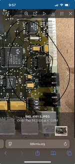
Hello folks! I'm working on bringing my college 1991 Macintosh Classic back to life. It suffered from leaking capacitors and was completely dead, so I decided to learn how to solder and did a complete recap of both the logic and analog boards and a through cleaning with 99% iso. After some reflowing of my amateurish soldering it came back to life in all regards except one - a complete lack of audio. At this point I am stuck. I have checked the speaker (resistance 61.5 ohms), tried using headphones (no sound), and desoldered, cleaned, and resoldered the UA5 sound chip twice. I cannot see any broken traces - is the sound chip simply dead? I am new to this, so any advice would be most welcome! I am attaching some photos of the logic board as it currently sits.

Many thanks!

Otho


IMG_4081 2.JPEGIMG_4082.JPEG
 
You might in a worse case scenario have to remove sound chip and clean pads/legs and repair traces. Check top of legs to the pads on sound chip and then legs / pads to vias / caps. Sometimes its best to check these before new caps are put on as the broken trace can be right underneath due to cap leakage.

Good job by the way:) always fun to try and fix up and old mac
 

Attachments

  • IMG_8816.jpeg
    IMG_8816.jpeg
    689.6 KB · Views: 12
You might in a worse case scenario have to remove sound chip and clean pads/legs and repair traces. Check top of legs to the pads on sound chip and then legs / pads to vias / caps. Sometimes its best to check these before new caps are put on as the broken trace can be right underneath due to cap leakage.

Good job by the way:) always fun to try and fix up and old mac
Agreed, and will do! I haven’t found any broken traces yet, but I will stick to it. I’m focusing on the C3 cap and UA5 chip just as you suggest. Many thanks - been a real trip bringing this back to life and reading through 30+ year old files on it.
 
For something like this, I normally remove the chips in question, clean the pads, then take a meter and check from pad to via, or from pad to destination pad of another chip. I find that it's pretty common to have a hair line crack right between the pad and the trace. Often they are small enough to not see without magnification, but large enough to require a jumper wire instead of a solder blob. I use .1mm magnet wire to jump them.
 
Folks,

Many thanks for all the tips! I'll doublecheck C1, and have begun desoldering various chips and caps and checking the traces. I acquired an upgraded multimeter today to help check continuity. A good project to learn on - I will keep you posted!

Otho
 
One more thing. Make sure the contacts in the audio jack are working. There are slider contacts inside the switch ( you need to remove the switch to get to them ). Those contacts can get gummed up and if they are not working, you have no audio. Try it with something plugged into the jack and see if that helps. Also, the traces leading to the audio jack and also the ASC can get damaged. Check from pad to pad via the schematic to make sure the whole trace and it's pads are all connected. I've had hair line cracks right at the pad/trace junction that have given me hard times.
 
Back
Top