• Hello MLAers! We've re-enabled auto-approval for accounts. If you are still waiting on account approval, please check this thread for more information.

Dimmo 030 Accelerator

falen5

6502
Hi Folks

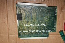
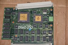
In a bit of a fix here - Just recapped the 5 smt caps off a Diimo 030 Accelerator.

When I powered it up it did not work.

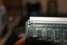
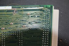
Then I noticed one of the caps on the back of the board is missing.
Possibly due to reseating the cpu

Has anyone any idea what value this cap is , or how I could find out

There are allot of these caps on the back of the board - They all look the same and none of them have any writing on them

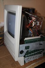
I have circled the missing cap in yellow

appreciate any advice on this folks
 

Attachments

  • a.jpg
    a.jpg
    3.7 MB · Views: 29
  • b.jpg
    b.jpg
    4.6 MB · Views: 26
Looks like the backside is all "decoupling" capacitors, which are probably all the same type. Remove another one and measure it out-of-circuit to find its value, then use the same again? That said, a single missing decoupling capacitor isn't quite likely to cause a straight-up failure like this. Did you accidentally bridge some pads to vias underneath the replacement capacitors or something?

As far as how the missing capacitor was removed, it is very close to C5. The heat of reworking C5 could have weakened the solder around the missing capacitor temporarily, making it easy to remove by accident.
Thanks for that nyef

Heres what happened.
I removed all 5 old caps , removed old solder with wik , put on the 5 new caps using minimum solder - all looked good but wouldnt work

inspected entire board under magnafying glass - would not work

removed caps 1 by 1 to make sure i did not bridge anything , and put them back on

still did not work

removed math co processor - did not work - put it back in
then I reseated the cpu

The cpu needs a good bit of force to be put in fully and the missing cap is just under the cpu

still didnt work

then i noticed 3 of the pins in the PDS connector were after being pushed back - thought i found the problem - pushed them back into their
correct position but it would still not work

then I saw the missing cap

.............

So i have to remove one of these decoupling caps and measure its capacitance value ?

just looked again and there is no writing on these tiny things , no sign of polarity , anything !!!
 
Yes, they are decoupling caps, value is 100nf, nonpolarized ceramic MLCC. However, that cap is in no way essential to the card working so it is not your problem. All the caps on the card are non-essential, actually, and it should work (temporarily) without them for the sake of testing as long as your PSU is decent.

I double check the caps again, taking a very, very close look at the traces in proximity to each of the larger caps you installed as that's your best odds for inadvertent damage or bridging assuming card was working fine beforehand. You might also check that you don't have any broken solder joints on the bottom connector also.
 
Thanks for that Zig.

Ive recapped many macs , pretty tidy with the iron.
Ive metered all the caps from cap terminal to pad to corisponding via - they all check out.

I noticed the green mask was gone on an area of the board , right next to one of the holes for bolting the card to the macs frame ( circled in yellow)

I guess this happened from the card not being fitted correctly

will have to meter all these traces for any breaks

What would be the best procedure to restore this area of the board , these exposed traces - run solder over them and then some varnish or something ?

also a pic of what I thought was the problem , PDS pins pushed back , but when put them back in their correct position it still didnt work

im 99.9% my recap is good - I recapped it last night and when it didnt work I removed the caps one by one checking for any accidental bridging but there was none - I dont want to be putting any more heat on the pads

Had a look at the pins on the PDS connector - think ill reflow them all
 

Attachments

  • 11.jpg
    11.jpg
    2.6 MB · Views: 18
  • 22.jpg
    22.jpg
    3.8 MB · Views: 16
Happy to report it was the PDF connector

I reflowed all the pins and the accelerator is now working , even with one of those decoupling caps missing , so nyef and zig were spot on !!!

I didnt see any cracks in the solder on the pins with a magnafying glass but reflowed them all anyway

it worked

Should I put some clear varnish of those exposed traces ? , and what about that missing decoupling cap ? - I just want to put the bucket back on and never open it up again !!!

Thanks for all your help folks - Love this place !!!!
 

Attachments

  • working.jpg
    working.jpg
    2.8 MB · Views: 16
Glad to hear you got it sorted.

You should find a thin bit of plastic to go over that area. Some packing tape would even work. The design guide for SE/30 cards specifies where the card contacts the chassis, it is supposed to be a no-trace zone with a ground pad, but this wasn't always done; commonly a piece of plastic insulation is used instead and I think that is what is supposed to be there on a Diimo. To protect exposed copper, I tend to use overcoat pens or tin the traces, but the reality is some nail polish would work just fine too.

The missing cap isn't really important; you can substitute any ceramic cap that you have handy which fits the footprint and is 100nf to 1uF or so if you want to replace it.
 
Your right Zig

There are 2 clear plastic insulators stuck to the board in the exact area where the metal tabs come into contact with the board.
they are on the opposite sides of the board as this is how the card is supposed to be installed ( one tab behind the board , the other in front of the board ) so the exposed traces are not touching anything when installed correctly.

Ill slap some clear nail polish over the exposed traces anyway

as for the missing cap , the card seems to have worked this long without it , and I aint feeling lucky !!!

cheers man
 
Back
Top