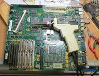
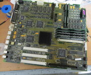
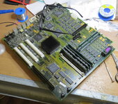
I carefully desoldered the ROM socket from my Quadra 700 motherboard and soldered it into my Quadra 650 motherboard.
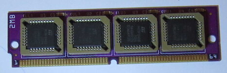
I also have a 2MB ROM SIMM module that I bought for my IIsi. It contains four M29F040-70 flash chips, so I can reprogram the chips ...
I'm now looking for a patched ROM for my Quadra 650 where the memory test is disabled and I can use four 128MB SIMM modules ...
How can I divide it into four sections? I suspect it will only result in four 256k sections, but I need four 512k sections. Can I simply fill them on the top with FF ...?
LL = low
UL = upper low
LU = lower high
UU = high
...is this correct?
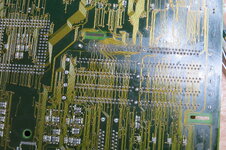
I read that the ROM 2MB Modul I have (see the picture) is not Compatible with the Quadra ROM SIMM slot/socket ...? Have I to patch the Modul I have?
I also have a 2MB ROM SIMM module that I bought for my IIsi. It contains four M29F040-70 flash chips, so I can reprogram the chips ...
I'm now looking for a patched ROM for my Quadra 650 where the memory test is disabled and I can use four 128MB SIMM modules ...
How can I divide it into four sections? I suspect it will only result in four 256k sections, but I need four 512k sections. Can I simply fill them on the top with FF ...?
LL = low
UL = upper low
LU = lower high
UU = high
...is this correct?
I read that the ROM 2MB Modul I have (see the picture) is not Compatible with the Quadra ROM SIMM slot/socket ...? Have I to patch the Modul I have?