• Updated 2023-07-12: Hello, Guest! Welcome back, and be sure to check out this follow-up post about our outage a week or so ago.

Twentieth Anniversary Mac PSU replacement

GRudolf94

Well-known member
Well, one of the wires should have a voltage at all times. I thought it was yellow. In any case, it is probably one of the wires that are the only one of its color. If not, then you have more troubleshooting to do. The normal order would be to go from the diode bridge forwards, but it could be that the PWM (the TOP226) failed as discussed previously, as it's one of the most sensitive parts in there, and there was an overvolt condition.
 

chrisrueckert

Well-known member
MOVs do have a lifespan so thats not surprising. Also a surge could have done this as well.

the TOP226Y and 1ohm fusible resistor are a known weak spot in these PSUs, knocking out standby voltage. When the TOP controller fails, it opens the 1ohm resistor.
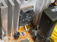
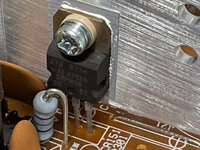
Could you point me to the location on the board where I could find the TOP226Y? I found a few similar ones but not this particular part:

IMG_1166.jpg
IMG_1167.jpg
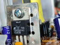
IMG_1170.jpg
IMG20230805200003.jpg
 

chrisrueckert

Well-known member
Ok, so I switched the TOP200. No success.

Coming back to the task to measure the voltage of the yellow wires: Which one of the following table do we want to measure?

Pin​
ConnectorLabel
1​
J2 Pin 7AMP OE
2​
3​
J2 Pin 14AMP RHS
4​
5​
J2 Pin 10SPKR RHS
6​
J2 Pin 9SPKR RTRN
7​
J2 Pin 8SPKR LHS
8​
J2 Pin 12AMP RTRN
9​
J2 Pin 13AMP LHS
10​
J2 Pin 4PFW
11​
J2 Pin 6-12V
12​
J2 Pin 25V
13​
J16 Pin 25V
14​
J16 Pin 6GND
15​
J2 Pin 3GND
16​
17​
J2 Pin 15V
18​
J16 Pin 35V
19​
J16 Pin 7GND
20​
GNDGND
21​
J16 Pin 8GND
22​
J16 Pin 112V
23​
J2 Pin 512V
 

techknight

Well-known member
Ok, so I switched the TOP200. No success.

Coming back to the task to measure the voltage of the yellow wires: Which one of the following table do we want to measure?

Pin​
ConnectorLabel
1​
J2 Pin 7AMP OE
2​
3​
J2 Pin 14AMP RHS
4​
5​
J2 Pin 10SPKR RHS
6​
J2 Pin 9SPKR RTRN
7​
J2 Pin 8SPKR LHS
8​
J2 Pin 12AMP RTRN
9​
J2 Pin 13AMP LHS
10​
J2 Pin 4PFW
11​
J2 Pin 6-12V
12​
J2 Pin 25V
13​
J16 Pin 25V
14​
J16 Pin 6GND
15​
J2 Pin 3GND
16​
17​
J2 Pin 15V
18​
J16 Pin 35V
19​
J16 Pin 7GND
20​
GNDGND
21​
J16 Pin 8GND
22​
J16 Pin 112V
23​
J2 Pin 512V

Did you actually test the 1 ohm resistor associated with it to see if it was open? because thats how you determine if the TOP Failed or not...
 

chrisrueckert

Well-known member
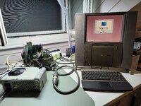
It is alive! Just realized that I forgot to connect one plug in the PSU. Thank you all provided here in this thread.IMG20230809221332.jpg
In summary, the overvoltage caused the MOV and TOP200 to fail. I sourced these parts from a DPS-150GB B PSU for a Performa 64/6500. Once these were replaced, the TAM works flawlessly.
 

Byrd

Well-known member
It's good to know the 6500 PSU is pretty much the same as what is housed in the TAM's sub box - are there any massive differences in the design?
 

Byrd

Well-known member
@chrisrueckert thanks for the link - I'm going to have to delve inside mine one day (fan seems suspect) - did you find any screws at the top under the rubber - or did it all come apart prying the base off?
 

chrisrueckert

Well-known member
Some of the screws are under the rubber. You'll probably feel them then you push the rubber a bit. Their position is the same as with the P6500 PSU. Note the additional two screws holding the transformer in the TAM PSU but you won't need to loosen them to remove the case.
 
Top