• Updated 2023-07-12: Hello, Guest! Welcome back, and be sure to check out this follow-up post about our outage a week or so ago.

Torn pad on Performa 475

D-50 Dude

Active member
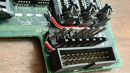
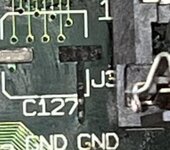
I was removing capacitors in preparation for the new ones I ordered when I pulled up a trace. I was working by the Ram slots and didn’t want to use a lot of heat which was a mistake. I tore it up pretty badly too so I don’t know if it’ll be repairable, but I would be appreciative of any help. Thanks!
 

Attachments

  • 7B62D266-385A-4C9A-9CDE-48C460CC5339.jpeg
    7B62D266-385A-4C9A-9CDE-48C460CC5339.jpeg
    254.8 KB · Views: 25
  • D1E8141F-ACC9-44C4-87F3-E2DFAED5D5BE.jpeg
    D1E8141F-ACC9-44C4-87F3-E2DFAED5D5BE.jpeg
    254.8 KB · Views: 19
  • 94EC5C99-5A38-4E5D-918B-F1B627413876.jpeg
    94EC5C99-5A38-4E5D-918B-F1B627413876.jpeg
    828.2 KB · Views: 23

Phipli

Well-known member
It will be fine. You can fashion a new one from a component leg and run it to the nearest place there is metal. You can use a scalpel to scrape of the solder resist if needed, for example from a trace or a via.

It happens, more often than people care to admit :) Sometimes the cap juice makea boards more prone to it, sometimes... you just get it wrong.
 

D-50 Dude

Active member
I have an idea how I’m going to do this but I wanted to run it by you. My plan is to glue a lead to the board and solder the lead of the capacitor to one side of the glued lead then solder a wire from the other side of the lead to the ground on the power connector.
 

AndiS

Well-known member
It happens, more often than people care to admit
True!

Last year I recapped an Amiga 500 board and boy do these have good ground. It takes away heat faster than any board I've subjected to a soldering iron before. So I also tore off two pads. Luckily it is the ground pads that are problematic because of their heat capacity via the connected ground layer. So it is easy to find an adjacent component and connect the cap lead there.

Then you can decide if you want to speak of it - or not ;-)
 

Phipli

Well-known member
I have an idea how I’m going to do this but I wanted to run it by you. My plan is to glue a lead to the board and solder the lead of the capacitor to one side of the glued lead then solder a wire from the other side of the lead to the ground on the power connector.
You don't need the glue. I'd solder down the cap bend an "L" on the end of a wire and solder it to the broken pad side of the cap, then run it to where ever you want to get ground from. You could even solder to the cap before soldering the other side down.
 

D-50 Dude

Active member
At the moment my problem is my equipment. All I have is a hot air station and a cheap Walmart soldering iron. The hot air station works great when all goes according to plan especially since I use solder paste. However for doing small repairs that wouldn’t work great with the hot air station, it’s a little more difficult. I also have a Hakko battery powered soldering iron, but I’ve misplaced it, so all I have to work with is the crummy Walmart one. I’ll try to look for it so I can solder the ground wire to the new capacitor.
 

D-50 Dude

Active member
Another quick question, for future reference, what temperature should I set my hot air station to for desoldering/soldering? 370F is what it was set at when I tore up the pad.
 

Phipli

Well-known member
Another quick question, for future reference, what temperature should I set my hot air station to for desoldering/soldering? 370F is what it was set at when I tore up the pad.
I tend to use mine at 300C (690F???) Are you sure yours isn't in C???

I would have thought you'd struggle to melt solder at 370F
 

D-50 Dude

Active member
Yup. It was set to F. And yes I was indeed struggling to melt solder. It melted the flux just fine although I guess that’s to be expected. I will be sure to use 572F in the future. This is my second time doing this sort of project, so I’m still a beginner and I appreciate the help :). I don’t even remember what temp I used when recapping my IIcx, which was my first project.
 

joshc

Well-known member
A cheap iron will struggle to maintain temperature so you may have to go hotter. Practice on something you don't value if you're not sure. I tend to solder at a higher temp than most, around 390C but I don't apply the iron for very long when doing SMD work.
 

Phipli

Well-known member
A cheap iron will struggle to maintain temperature so you may have to go hotter. Practice on something you don't value if you're not sure. I tend to solder at a higher temp than most, around 390C but I don't apply the iron for very long when doing SMD work.
Hum, 300C is already quite high (because I'm lazy regarding switching it up for ground plains). But lower power irons struggle more like you say.

I'd start lower and work higher if needed.
 

D-50 Dude

Active member
Good point. Would something like this work?
 

Attachments

  • 9C8A94FD-C75D-4741-9563-65CFDB65CA7A.jpeg
    9C8A94FD-C75D-4741-9563-65CFDB65CA7A.jpeg
    1.8 MB · Views: 14

D-50 Dude

Active member
Alright I now have the other end on the bottom side of the board. The reason I have it wrapped around is for extra durability.
 

D-50 Dude

Active member
I got all the caps installed and redid the jumper wire solution. Unfortunately, the power supply decided to quit. I made the mistake of opening it to check the caps. They looked good so I put it back together. I must’ve done something wrong however, because now the power supply just makes a clicking sound (regardless of whether or not it’s connect to the logic board). When connected, the speaker just makes a popping sound in time with the clicking of the PSU.
 
Top