• Updated 2023-07-12: Hello, Guest! Welcome back, and be sure to check out this follow-up post about our outage a week or so ago.

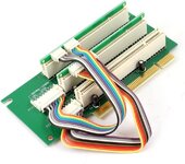
Three Slot Riser for 6400 - In search of the Mythical Slot C

Trash80toHP_Mini

NIGHT STALKER
View attachment 24449

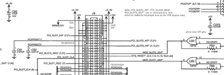
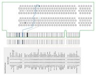
The connector at the bottom has 194 pins, 97 on each side.    The pins aren't numbered in silk screen, so for my purposes, I numbered them from left to right on the front.   On the back, I did not flip the card over.   Pretend you're looking through the board, oriented as above, and the back pins are left to right, 98 - 194.     So pin 98 is opposite pin 1.  Pin 194 is opposite pin 97, in my system.

Pins run:  1 - 42, 43 - 87, 88 - 97;    98 - 139, 140 - 184, 185 - 194

where commas are the slot notches.

I found the following:

Pin 114         Slot C interrupt

Pin 113         Slot A interrupt

Pin 17           Slot B interrupt

Pin 76           Slot A REQ

Pin 77           Slot B REQ

Pin 79           Slot C REQ

Pin 174         Slot A GNT

Pin 175         Slot B GNT

Pin 177         Slot C GNT

Pin 153         Slot A IDSEL, ADD 13

Pin 55           Slot B IDSEL, ADD 14

Pin 151         Slot C IDSEL, ADD 15


Wow, that pinout is nothing like any standard of which I'm aware. Is that implemented on a single connector on the logic board or abutted connectors?

Anyway for the first three above, I found a pin on the comm slot which connected to what ought to be the next pin in the sequence of interrupts, GNTs or REQs.  I didn't check IDSEL.   So I strongly suspect it's an independent PCI slot.    Umax did some unnatural stuff on the S900, where the sold a combo U2 LVD SCSI card with 10/100 ethernet on board.   It only worked in slot 1 of the S900 and there was an extra little connector at the end of the PCI slot to provide extra signals to support the ethernet portion.  Then there was a hacked to the gills driver that added an OF script when made the ethernet portion appear as slot E, which is some kind of special legacy slot in the firmware or some such.  
Slot 1 = another connector on the Logic Board or ComSlot on the riser?

Slot E1 is the normal location of the CS2 EtherNet card. I imagine the OF script would be a system patch for the SCSI half of the card. I wonder how TattleTech reports the SCSI setup, if at all? A parallel might be the Futura II VidCard/EtherNet daughtercard combo which shared the same NuBus Slot ID?

Have you run TattleTech to see if the SCSI portion might be located at Slot D1? The PCI report might show D1 as available without having the card installed. D1 is a curious gap in the ID sequence of Alchemy. It's probably more likely that the SCSI implementation shares E1 though.

But it wouldn't make any sense for the C600 to use a similar system because anybody's card might be installed in the comm slot.  The E100 card, as it was called, was the only card that could use that extra connector in the S900.
That extra connector has how many pins? ComSlot2 connector is shorted six connections of a PCI connector and a gaggle of connections are dedicated to the CS2 modem. So the second connector probably fleshes CS2 out so as to support the full PCI spec?

Do the PM6400 and PM6500 use the same 194 pin connector for their riser cards?
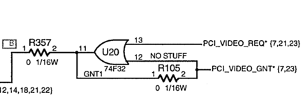
Not even close. It's a standard PCI connector, but at least one reserved pins isn't, it's a direct connection to the REQ pin of Slot B1. INT A and INT C are connected to A5 which is +5V holding the coding high on Slot B1.

Haven't worked on Slot A1 yet other than to successfully install a VidCard directly into the MoBo sans riser.

All RA Rackmount risers I've tested appear to function as slot A1, with one possible exception. Can't put my hands on it for testing, hopefully it will turn up and not be the same card as another I'm trying to re-locate in hopes of modifying it to Slot B1 function. If/when I can do that, I should be able to spec the TwinSlot riser for TAM and the other single slot riser limited Macs. After that I can start playing Slot C1 mix-n-match games.

When you have a chance, could you buzz the connections between connectors for Slots C1, B1 and A1 to identify which lines on C1 are unconnected to either of the other two. Fifteen drop out between A1 and B1. I'll post a table when I can sort a couple of things out. The dropouts should be located between A6/B6 and A19/B19. The only outlier will almost certainly be the REQ line at A26. Which "Reserved" line Apple intended (provided?) for that one on the logic board riser slot is the mystery.

 

Trash80toHP_Mini

NIGHT STALKER
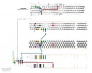
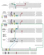
At long last, I've rendered the mess of boards, tables, doodles and pinouts spinning around in my head down into a single markup sheet! :blink:

ABCE-RiserProj-000.jpg

View attachment ABCE-RiserProj-000.PDF

@trag any chance you can shed some light on how INT A-D are implemented on a logic board so as to define a Slot ID?

If we can noodle the mystery of those four lines out, aside from the 3.3V sense lines, the other three inputs are available on the CommSlot to implement Slot E1 on a riser. If I can't find REQ/SEL for C1 on the 6x00 connector, it may come to that, but four slots would be better. [:)]

 
Last edited by a moderator:

trag

Well-known member
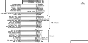
In any given PCI slot, Apple has traditionally (in this generation, don't know about Intel and late PPC stuff) wired all four INTs together.   So there's a single unique INT per PCI slot.   Every slot has it's own unique INT.   So, when the interrupt manager (e.g. Grand Central on X500/X600) receives an interrupt, it knows exactly which slot it came from.    So, my guess is that  your PCI header on the 6400/6500 logic board runs a unique INT to each of the four INT pins in the header slot, but then runs just one of those four to each PCI slot on the riser card.  So each PCI slot on the riser card gets its own unique INT from the header slot and uses that one INT for all four INT pins in the slot.    

They would still need to steal some unused pins in that PCI header to provide Bus Grant and Bus Request lines to each of the riser card slots.

ASIDE:  This actually is a terrible way to do things, because the PCI spec. includes provisions for PCI-PCI Bridges to expand one PCI slot into up to 16 additional slots.    If one has installed a PCI-PCI Bridge all of its sub slots use the interrupt/interrupts available in the original slot.   If the OS is expecting to identify the slot from the unique interrupt, this doesn't support the spec. very well.     Apple's implementation does support a single layer of PCI-PCI Bridge, as far as I can tell, but it fails when one tries to have a bridge behind a bridge, which is also supported in the specification.   I suspect this Apple bug is related to how they rely on the uniqueness of their interrupts, but I'm not certain.

They should be identifying slots purely through the IDSEL system.

 
Last edited by a moderator:

Trash80toHP_Mini

NIGHT STALKER
@trag Thanks, that explains quite a bit. Neither of the upper slots on the "Black Magic" riser will work when it's installed in any of the Beige G3's PCI slots. Not implementing PCI slots as intended in that manner jibes with Apple's substandardization history. Gotta recheck it. ISTR the Slot ID being passed on from the motherboard to the bottom slot, but I forget.

ISTR there being a total cutout between the four INT lines of Slot B1 from both Slot A1 AND the edge connector. I'll be rechecking that next.

Methinks they may be using the unique (hijacked reserved contact) SEL line (Init Device Select) as the Slot ID mechanism


Trash80toHP_Mini

NIGHT STALKER
All four INT lines are tied together on Slot B1. They connect to the edgecard at A9  .  .  .  which is RESERVED of course! :approve:

That's two down now, just four more RESERVED lines  .  .  .  in my reserve. [:D]


Trash80toHP_Mini

NIGHT STALKER
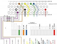
@trag I think I may have cracked stealing Slot E1 for my multiple slot riser from CSII?

Do you think the INT~ line on the ComSlot II connector could be the equivalent of the unified INT A-D lines of the substandard Mac PCI Slot implementation?

Slot_E1_000.jpg

View attachment Slot_E1_000.PDF

Slot C1 lines may or may not be present on the 6x00 riser connector, but If I can implement Slot E1 on an A/B header with nubbin card jumpers from CSII as a Mini PCI Slot on the solder side of the riser as I've diagrammed elsewhere, that'd be three slots in every Mac of this the series, including the TAM.

Gotta noodle out the 3.3V lines, figured on doing that last. Got that info handy in your noggin?

Edit: Configuring Slot B1 requires hacking into the generic three slot riser's "reserved" edgecard contacts. I've got a nubbin card made from a LittleRedRiser set to wire up CSII for a first run/hail Mary as it's much easier to implement. Any help on 3.3V voodoo would be much appreciated.

 
Last edited by a moderator:

Trash80toHP_Mini

NIGHT STALKER
OK this is officially out of hand, from the DevNote's description of the PCI Signals::

IDSEL -  Initialization device select; used during configuration

It's fine on A1 (bottom slot) showing right up where it's supposed to on the edge card connector.

IDSEL on B1 (top slot) is another story entirely, the dang thing is tied to Address Line 14 on the 6400 riser! 8-o

So during bootup/setup, the system uses A14 to figure out how to talk to a card installed in Slot B1? And here I was thinking there weren't all that many "RESERVED" pins remaining to work through in search of the mythical Slot C1.  :lol:

One might assume this makes some perverted kind of sense, but  .  .  .


trag

Well-known member
IDSEL's are always wired to an address line.  That's how PCI works.  It's weird, but it makes sense.   I just can't remember how at the moment, or I'd wander off into one of my long explanations.  IIRC, it has something to do with holding some command lines a certain way at initialization and then walking the address lines until a slot sees it on their IDSEL line and responds.

Anyway, from what I saw in the C600 riser, I think you'll find IDSEL for slot A goes to address 13, slot B to address 14, slot C to address 15, and I bet whichever pin is used for IDSEL in the comm slot goes to add 16.


Trash80toHP_Mini

NIGHT STALKER
THX, that now makes a lot of sense to me in terms of the cascading nature of PCI slot addressing voodoo.

I took a quick look at the remaining lines that are cutout between A1 and B1. Notes are at work for later perusal and I don't remember offhand if it's either PRSNT1 or PRSNT2 that appears to be problematic. Slot A1 connects to the proper contact on the edgecard, but on B1 that pin seems to drop off the ends of the earth. Weird stuff.

It's currently looking like hijacking Slot E1 might be a more productive avenue of approach than the Slot C1 quest.


Trash80toHP_Mini

NIGHT STALKER
OOPSIE! That comma wasn't helpful at all. ::)

View attachment wiremess-000.pdf

I've got most of it worked out in a convoluted mess of a diagrams, doodles and tables, but now I've narrowed it down to something practical. I can begin prototyping by hacking together a pair of Flex-Cable PCI Risers, adding a jumper block configuration setup. The few CS2 edge connector lines from that beheaded riser will be woven through the web of the modified PCI Slot riser. the setup will allow testing the Slot B1 patch and an attempt to blow ComSlot2 out to full spec PCI Slot E1 in the same connector bolted up to the side panel of the BenchMac 6500.

Then/if/when, I can poke around for the missing lines for Slot C1. The info that IDSEL is tied to A15 is a major step of that campaign, THX, trag! Time for more doodling at work.

 
Last edited by a moderator:

Trash80toHP_Mini

NIGHT STALKER
FAIL - first stab at converting the ComSlotII to a full PCI Slot didn't work, but I really wasn'texpecting it to work right out of the gate, if ever.

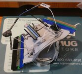
Flexible ribbon cable risers came in today for converting Slot A1 to B1 and to poke around looking for C1, but it's a little complicated to jump right into. So I couldn't resist cobbling together a ComSloII riser to jumper the four required signal lines (Green, Orange, Blue, Red) to the header block of the jumper configurable three slot riser. Oh well, we'll see what the next setup yields.

@trag  I left the 3.3V Key pins (A12/A13/B12/B13) floating on the first try and grounded them on the second. Didn't figure it mattered because a 3.3V slotted riser works fine as A1. Does it matter after all? Gotta get B1 right for the low profile twin slot adapter. C1's a unicorn hunt.

 
Top