Phipli
Well-known member
If you're worried about it and want to just test it, normally pin 1 on the clock is an enable pin, if you bridge it to ground (the other pin on the same side, as in, next going anticlockwise) it disables the clock's output. The next anticlockwise pin is the clock output, and the last is 5v.That's right!(Upgraded from LC to a full 040, new one is actually rated 25Mhz but haven't figured out if I could swap the oscillator on board to up it all the way to 25...)
If you connect a 12.5mhz clock to the ground, output and 5v pins, you can "inject" the higher clock speed. This is basically what old clock chip kits did.
Removing the extra stuff reverts back to stock.
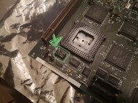
The clock in question is here on my 25mhz 610 board :

(PS I didn't recap thia board - although I did borrow the 31.3344MHz clock to get an LC 475 running)

