Skate323k137
Well-known member
Recently @jajan547 posted in another thread about Mike Willegal's "Brain Board" for Apple II computers. The two of us decided it would be worthwhile to split a JLCPCB order. Mike abandoned this project years ago, but in doing so, he also generously made the files and source public.
This board allows an Apple II / II+ / IIe to act like an Apple 1, including cassette driver.
The first hurdle was that the gerber files didn't want to process right on modern manufacturers. Ultimately here is how I fixed the files from Mikes site:
-Downloaded Osmond (Free PCB making software)
-Opened the osmond file from Mike's site, and then set the project dimensions/grid to mm in the menu (likely optional)
-Before exporting the gerbers, you have to use the menu to edit the filenames. The main thing is setting the right file extension for each layer, as Osmond has the same by default. This guide has a table at the top which should work: https://support.jlcpcb.com/article/29-suggested-naming-patterns
-Unfortunately there is some trace text outside the footprint of the entire PCB I cannot locate in osmond. This causes problems at JLCPCB but not PCBWAY.
-Exported the gerber files with aux 1 as board outline, deleting aux 2 layer file entirely.
Once that was all set, we ordered some from PCBWay.

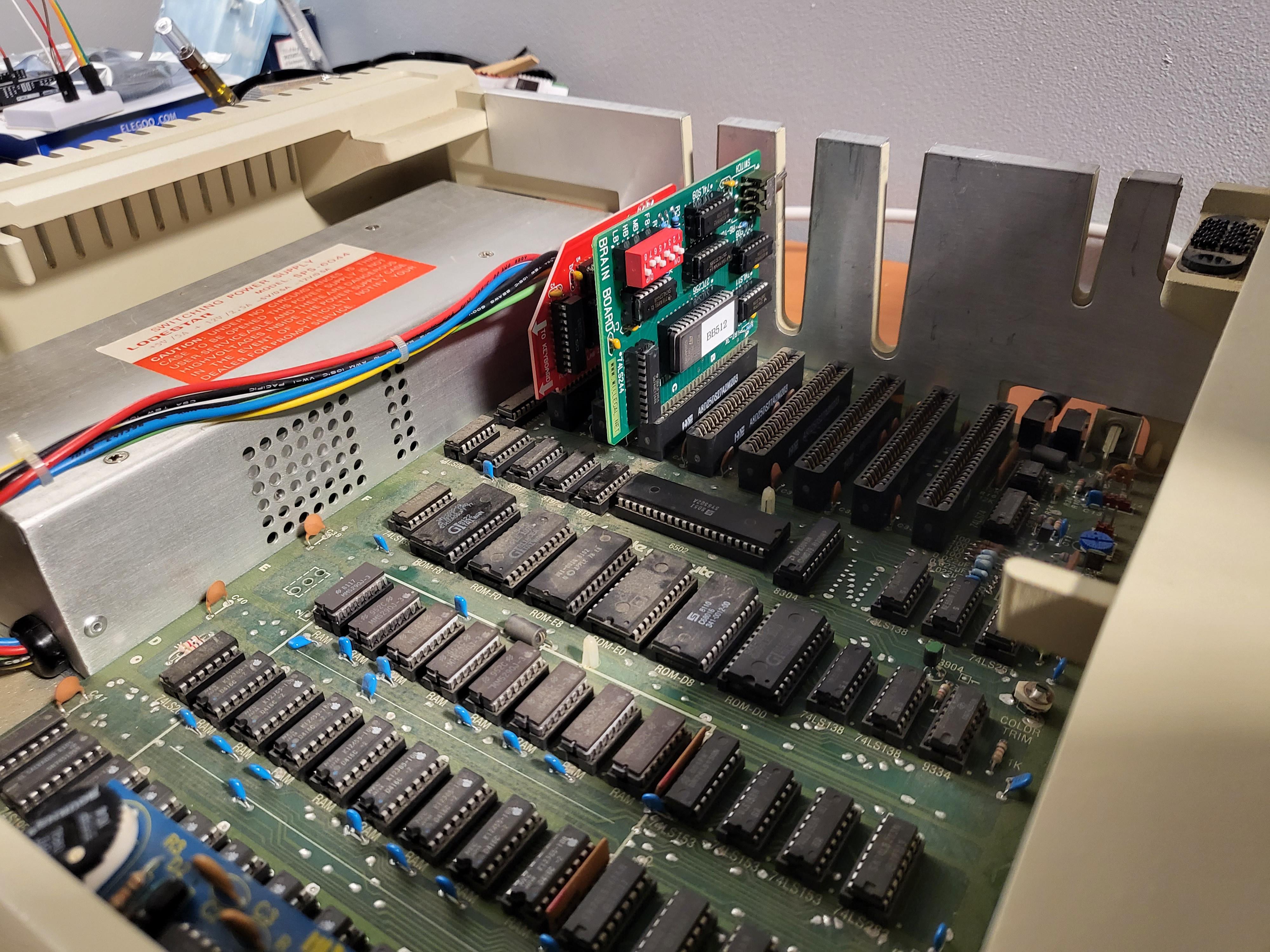
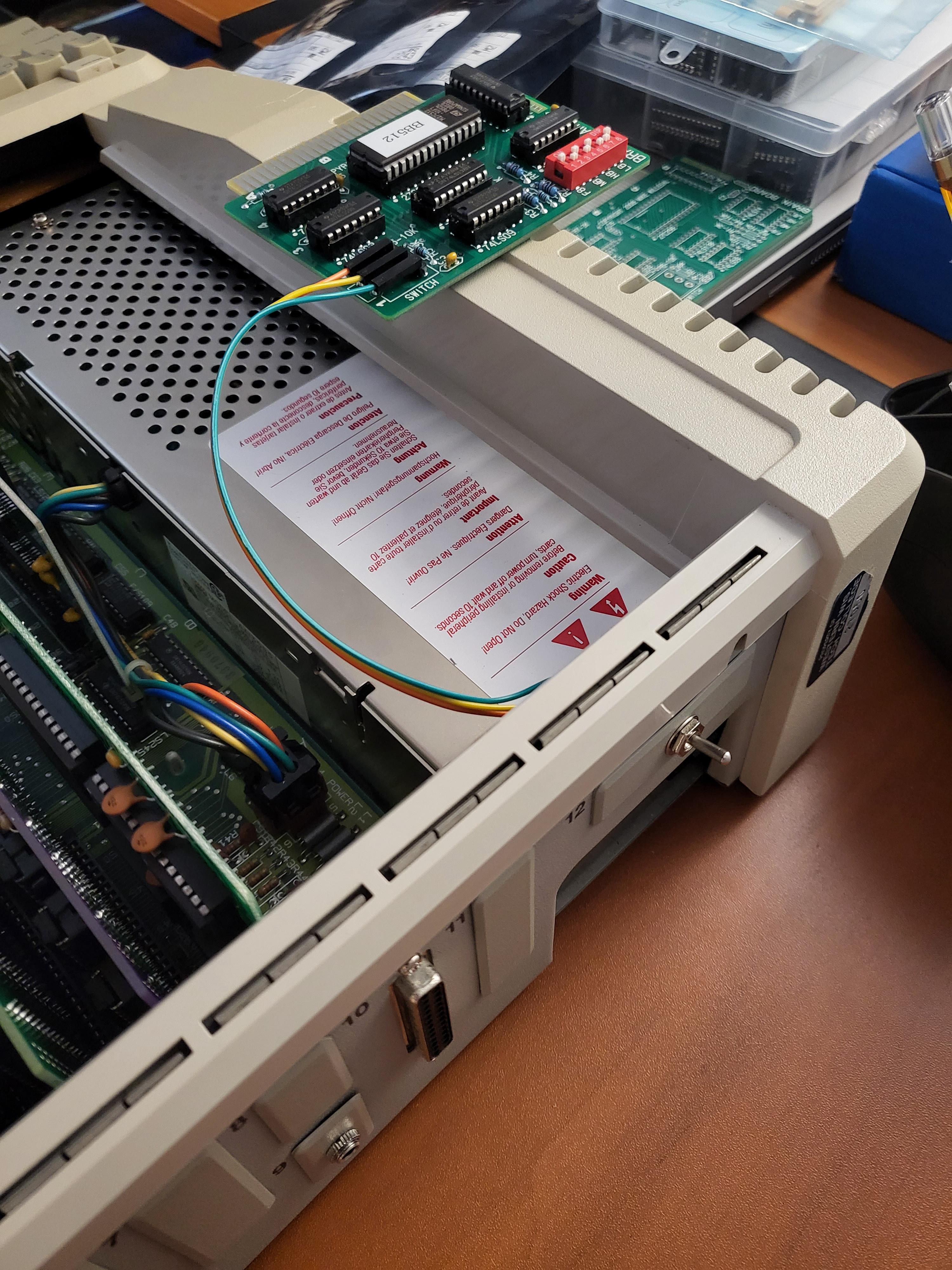
I received these this last Saturday and built 2 units; one with a switch on the card, one with pin headers for a remote switch. Apple II+ slots can allow access to a soldered on switch, but systems like IIe the switch is very tight against the back of the system and I recommend pin headers and a remote switch. Take 5 right angle headers (normal pin headers like for hdd jumpers, but right angle), extract pins 2 and 4, and then solder it in. See photos. I used a sideways jumper to hold the pins parallel to the PCB while soldering on the header.


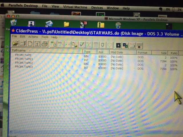
I tested using a couple pieces of Apple 1 software; I keep an iPod full of Apple 1 software handy for my Replica 1 plus which has a cassette interface. Overall the thing works as expected. Even in my IIe systems with tons of expansions, the only conflict I had was with this in slot 5, trying to boot CP/M from floppy in slot 6 (that CP/M card itself is in slot 3), when it initialized drivers it dropped me to an Apple 1 startup. I wager if I can get it into slot 1 it may fix this, but I would have to shave my uthernet connector that is in the way.


At this point I am modifying the PCB design to use a 27c512, as there was one unused dip (#2), and another person had done this modification in practice just not to the fabricated PCB design: https://www.applefritter.com/comment/83113#comment-83113
I've revised it in Osmond; once Macnoyd has a chance to double check it, I'll probably order some new/revised "Brain Board ][" PCBs intended for the larger ROM.
Here's a little video of the ASCII art displaying from the Apple 30th Anniversary program.
Thanks to @jajan547 for inspiring the revival of this project and macnoyd on AppleFritter for providing his concatenated ROM file and details of the physical bank switch to save us some time.
Attached to this post for convenience of anyone else is an updated copy of the Gerbers which worked fine at PCBWAY. Again, JLCPCB gets the wrong dimensions due to an issue I cannot find/fix in Osmond (text far outside the PCB outline) which does not impact PCBWAY. Also PCBWay has an option to bevel the PCB edge connector; this worked as well.
This board allows an Apple II / II+ / IIe to act like an Apple 1, including cassette driver.
The first hurdle was that the gerber files didn't want to process right on modern manufacturers. Ultimately here is how I fixed the files from Mikes site:
-Downloaded Osmond (Free PCB making software)
-Opened the osmond file from Mike's site, and then set the project dimensions/grid to mm in the menu (likely optional)
-Before exporting the gerbers, you have to use the menu to edit the filenames. The main thing is setting the right file extension for each layer, as Osmond has the same by default. This guide has a table at the top which should work: https://support.jlcpcb.com/article/29-suggested-naming-patterns
-Unfortunately there is some trace text outside the footprint of the entire PCB I cannot locate in osmond. This causes problems at JLCPCB but not PCBWAY.
-Exported the gerber files with aux 1 as board outline, deleting aux 2 layer file entirely.
Once that was all set, we ordered some from PCBWay.
I received these this last Saturday and built 2 units; one with a switch on the card, one with pin headers for a remote switch. Apple II+ slots can allow access to a soldered on switch, but systems like IIe the switch is very tight against the back of the system and I recommend pin headers and a remote switch. Take 5 right angle headers (normal pin headers like for hdd jumpers, but right angle), extract pins 2 and 4, and then solder it in. See photos. I used a sideways jumper to hold the pins parallel to the PCB while soldering on the header.
I tested using a couple pieces of Apple 1 software; I keep an iPod full of Apple 1 software handy for my Replica 1 plus which has a cassette interface. Overall the thing works as expected. Even in my IIe systems with tons of expansions, the only conflict I had was with this in slot 5, trying to boot CP/M from floppy in slot 6 (that CP/M card itself is in slot 3), when it initialized drivers it dropped me to an Apple 1 startup. I wager if I can get it into slot 1 it may fix this, but I would have to shave my uthernet connector that is in the way.
At this point I am modifying the PCB design to use a 27c512, as there was one unused dip (#2), and another person had done this modification in practice just not to the fabricated PCB design: https://www.applefritter.com/comment/83113#comment-83113
I've revised it in Osmond; once Macnoyd has a chance to double check it, I'll probably order some new/revised "Brain Board ][" PCBs intended for the larger ROM.
Here's a little video of the ASCII art displaying from the Apple 30th Anniversary program.
Thanks to @jajan547 for inspiring the revival of this project and macnoyd on AppleFritter for providing his concatenated ROM file and details of the physical bank switch to save us some time.
Attached to this post for convenience of anyone else is an updated copy of the Gerbers which worked fine at PCBWAY. Again, JLCPCB gets the wrong dimensions due to an issue I cannot find/fix in Osmond (text far outside the PCB outline) which does not impact PCBWAY. Also PCBWay has an option to bevel the PCB edge connector; this worked as well.
") .
.