• Updated 2023-07-12: Hello, Guest! Welcome back, and be sure to check out this follow-up post about our outage a week or so ago.

Recapping a Connectix Quickcam

zigzagjoe

Well-known member
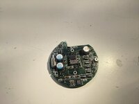
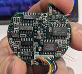
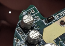
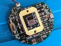
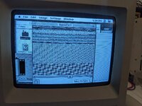
Yes, grayscale quickcams have caps - a lot of them. If yours displays digital garbage when opening up QuickPict, you probably need to recap it.
1698185350291.jpeg

How-to:
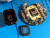
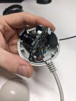
  1. How to open a quickcam. Be very careful with the clips!
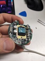
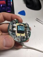
  2. Remove the lens and inspect the IR filter: mine was both loose and covered in cap juice.
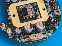
  3. Obtain appropriate caps. Below are the ones I used with digikey P/Ns.
  4. Perform the replacements. Remember that tantalum mark their positive side, where electrolytic mark the negative.
  5. Test. Hopefully, it works now.
Audio on mine did not really work post-recapping: a tantulum (nearest to mic connector) may not be appropriate for that specific use case. However, I tested by injecting audio and either I have additional problems with the ADC circuit, or the quality is so bad as to useless even when working well. I've attached a sample of Rob Zombie's dragula injected into pin 17 on the PIC (audio ADC). The opamp nearby is the preamp - all in all, a fairly standard mic circuit.

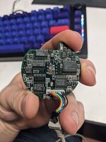
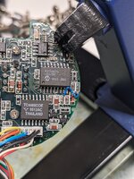
PXL_20231023_194127752.jpgPXL_20231017_232337084.jpgPXL_20231017_224429426(1).jpg


8x 718-1956-1-ND
Vishay Sprague 293D106X0016A2TE3
CAP TANT 10UF 20% 16V 1206

1x 565-HHXJ160ARA221MF80GCT-ND
Chemi-Con HHXJ160ARA221MF80G
CAP ALUM HYB 220UF 20% 16V SMD

2x 565-APXT6R3ARA331MF61GCT-ND
Chemi-Con APXT6R3ARA331MF61G
CAP ALUM POLY 330UF 20% 6.3V SMD
QuickPICT 4.jpgQuickPICT 2.jpg
 

Attachments

  • Connectix quickcam audio test.zip
    62.9 KB · Views: 3

LaPorta

Well-known member
Really neat! I believe I have a Color QuickCam USB version...I am sure it it somewhat similar. Thanks for the info, as I'll have to look into it.
 

zigzagjoe

Well-known member
Really neat! I believe I have a Color QuickCam USB version...I am sure it it somewhat similar. Thanks for the info, as I'll have to look into it.
Hopefully it is easier to open. These are a complete wiener to open (they are very well built, though!). You will break a clip on these, thankfully they aren't really needed due to how tight they fit together. I'm using a bit of acetone to reattach them - we'll see how well it works.

Also, voltages. The smaller caps are probably less important and voltages may vary. But the voltage on the big caps ought to be stable (and at the ICs).
Anoted voltages.jpgAnoted voltages 2.jpg
 

3lectr1cPPC

Well-known member
Can't be safe with any old tech it seems... hah.

Guess I should all the values to my website at some point, why not.
 

zigzagjoe

Well-known member
Yes, I was quite surprised at the number of caps inside. Though I suppose it makes sense: the serial ports aren't really up to providing power, so the circuit to harvest power off serial is complex, never mind the circuits to generate +- 3v for logic and +- 10v for the sensor.

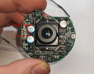
I did get the mic working after much hassle. The two audio caps (pictured below) may need to be electrolytic rather than the tantalums I put in at first. I seem to have been battling a bad solder joint elsewhere at the same time so I am not 100% certain on that ... but those caps should be cheap (just annoying to solder) it may be worth picking up a couple just in case.

1698288281931.png

Also, acetone to repair any broken clips does work. They will likely break if you open it again (it is not a gentle process), but you can just repair them again.
 
Last edited:

3lectr1cPPC

Well-known member
That thing looks like an absolute nightmare to solder to. There’s not much space in there for the caps on the right in your earlier image.
 

zigzagjoe

Well-known member
That thing looks like an absolute nightmare to solder to. There’s not much space in there for the caps on the right in your earlier image.

Thankfully, you can remove the lens with just a couple of screws and it makes it much easier to work with. You will want to do so anyways; the IR filter in mine was covered in crystalized cap juices 🤮

1698288395584.jpeg

What are you point to on the non-sensor side? Aren't those just traces?

Sorry, i should have been more clear - the intent is to show pairs of points to measure voltages on caps or leads of the ICs. I was a little sloppy with the arrows.
 

4seasonphoto

Well-known member
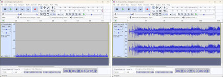
Wondering if you somehow introduced DC offset into your audio input? On the left is your audio sample. On the right is a normal, albeit 2-channel audio track.
Audio comparison.jpg
 

zigzagjoe

Well-known member
Wondering if you somehow introduced DC offset into your audio input? On the left is your audio sample. On the right is a normal, albeit 2-channel audio track.
View attachment 64334
Now that I'm actually thinking about it, given they are using a PIC's ADC to record the audio, sending my test signal without a DC offset into the ADC pin is going to sound off no matter what as it's going to clip the negative component. So that was my bad.

As far as the mic goes, after a lot of tinkering, cleanup, trace verification, swearing, and aforementioned electrolytic caps the mic is working as expected with it not being clear on the actual root cause. Audio quality is rather better than I expected, honestly.

I can tell you I hope to never open the dang thing ever again, though. Troubleshooting the mic was the most frustrating thing I've dealt with recently, and to add insult to injury when that panned out I found another issue causing images to seemingly lose their LSB that was resolved also with an unclear root cause during further troubleshooting efforts.
 

sfiera

Well-known member
Got one not so long ago which didn’t work with similar symptoms, but after opening it up (with one broken clip) the board didn’t look so bad to me. I didn’t feel up to dealing with all the little capacitors, so I set it aside for the time.

Anyway, after seeing this thread, I thought I’d take off the lens, and yeah, the IR filter has the same crud. It smelled pretty fishy when I tried to scrape it off, so I pulled off the capacitors too. Yeah, that’s worse than I had initially thought.
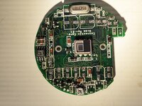
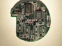
quickcam-1.jpgquickcam-2.jpg

Mine has three bodge wires, one of which seems to have carried some of the corrosion to the underside.
quickcam-3.jpgquickcam-4.jpg

So now to find time to clean it up, and order those replacement capacitors, and perhaps fix it.
 

zigzagjoe

Well-known member
That's the exact same as mine was - not obviously leaked, but start pulling caps off and it's obvious. Thankfully, the electrolyte doesn't seem nearly as corrosive as earlier ones so there wasn't actual damage. Interesting you've got a couple of bodges - must be an earlier rev.
 

zigzagjoe

Well-known member
More entries in the quickcam odyssey. The audio was back to being crap without anything having changed, but I decided to not do anything about it as it had quite frustrated me working on it previously.

Unfortunately, the quickcam fell on my desk earlier this week, which exposed a weak solder joint on a cap. Took it back apart, fixed that, but it was quirky again - sometimes starting, sometimes not, til it eventually quit working entirely. Generic troubleshooting for broken components, weak solder joints, removing and resoldering the ICs, checking voltages, etc, turned up nothing. Same static screen as in the original post - which seems to indicate an issue on the digital side of things. PIC not talking, or something similar. Checked all the caps (ceramic and electrolytic), resistors, etc - no progress. How frustrating.

Eventually I was about to quit and call it $20 down the drain. Which really pained me. Of course, this would be when I would finally get a flicker of life. Mr quickcam likes playing hard-to-get, after all. Further troubleshooting found if I death-squeezed a certain part of the board near the PIC, the camera would start and work normally. I verified this was not a mechanical issue (bad joint, broken trace, etc). So this only leaves the really weird option: my flesh was acting as a (poor) resistor and whatever was being bridged, it was enough to get the cam "booted" - after which it was fine.

Now, please don't get the impression that this is SOP for my troubleshooting processes, but in the name of science, in order to confirm the hypothesis: I moistened my finger (licked it) and touched the suspect area lightly.... it came right up. Repeatably. Hypothesis confirmed.

Some more probing after that found a 10k resistor between a certain capacitor beneath the PIC and +3v available on a diode nearby would bring the camera back to life. I have no idea why. This pin (RB6) seems to only be connected to pin 12 on the PIC, which is a GPIO without special function... but pulling it up to +3v available on the diode fixed my issue. YMMV

I'm deeming this the "sphere of hatred". I've devoted more energy into this ball than I did SE/30 logic boards.

1699574132031.jpeg

I have also attached a zip file with two logic analyzer captures of the quickcam being started by quickpict, previewing at full res for a few seconds, then capturing an image. DSview software required, available here.

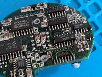
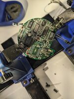
Further pictures underneath chips in case someone else gets deep into one of these. I left the crap chinese caps I fitted in the audio section as I have no interest in further troubleshooting to determine if the tantulums actually do or do not work there (seems I was battling multiple issues).

The potentiometer opposite from the crystal is used as a variable resistor and adjusts contrast. When adjusted properly (mostly a matter of trial and error, and personal preference) I saw about 14.3kohms on it. Can used any potentimeter 20k or greater to replace it. The adjustment range is fairly short. Too far and all goes gray (and never truly dark, despite the exposure values), too much the other way has no detail/is pure black and white.

QuickMovie supports live audio (Audio settings, on the audio menu) which is useful for testing.

Acetone works just fine to repair the clips. I recommend a little hotglue behind any repaired clips to reinforce them, see picture.

PXL_20231109_010102432.jpgPXL_20231109_010055841.jpgPXL_20231109_001320114.jpg1699575112656.jpeg
 

Attachments

  • Connectix Quickcam LA Captures DSview.zip
    25.4 MB · Views: 1
Last edited:

zigzagjoe

Well-known member
I hate myself. I got a Quickcam color. While it still worked, it was full of leaky caps. Here are the replacements:

capvoltageqtydiaheightdigikey
Sensor front330uF6v
2​
6.6​
8​
732-8475-1-ND
Sensor front220uf16v
1​
6.6​
8​
732-8524-1-ND
Sensor front10uf16v
1​
4​
5.5​
732-8518-1-ND
Sensor rear10uf16v
1​
4​
5.5​
732-8518-1-ND
FPGA rear10uf16v
2​
4​
5.5​
732-8518-1-ND

The IR filter was fogged by the capacitor residue, giving horrid image quality. I was able to find some 6.5mm diameter IR cut filters on amazon and glue it to the lens with B7000 (phone screen glue).

Note for replacements: 6.5mm is the minimum, and 10mm is the max for mounting on lens.
Or, if you want to use a rectangular glass, 13.75mm*17mm is the max that will work.
For an exact replacement: 13.3mm circular is the right size.
 
Top