mrpippy
Well-known member
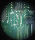
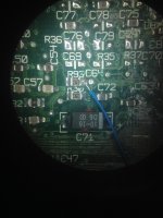
I've been recapping my Q605, some of the pads are in rough shape but I was still able to probe the connections easily. Here's the list I came up with:
C35: 47 µF (+): +5V (-): GND
C36 : 47 µF (+): +5V (-): GND
C101: 47 µF (+): 12V (-): GND
C105: 47 µF (+): +5V (-): GND
C127: 47 µF (+): GND (-): -5V
C128: 47 µF (+): 12V (-): GND
C129: 47 µF (+): +5V (-): GND
C136: 100 µF (+): +5V (-): GND
C137: 100 µF (+): GND (-): -5V
C149: 47 µF (+): C150 + (-): U30 pin 21
C150: 47µF (+): C149 + (-): U30 pin 24/25
C149/C150 are the ones I'm not sure about, especially the + side, I couldn't find any other point on the board that those two connect to. The trace between them does have a via which goes through to the bottom, but no traces coming out of the via.
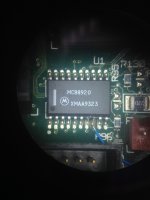
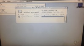
I've never gotten chimes or any signs of life out of this board, fan and HDD power up but no chimes before or after recapping, with a good battery installed. PSU voltages also look good even when the board is powered up.
I thought that some of the RAM vias/traces under C127/C128 would be bad, but I've tested the RAM signals and they all seem to be good. Anyone have any ideas?


