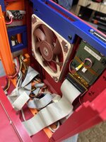
I would like to be able to travel with a 6200/5200. And so I am thinking if one could just take the logic board, and have e.g. 3d printed case to slot it in into, which hooks its pins up to to a small PSU, and IDE cable (+CF card adapter), and a mac-vga port.[[
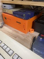
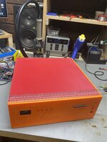
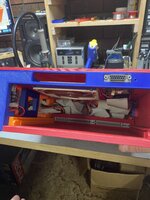
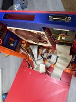
I saw this cool hack which has all the details for the PSU.
 68kmla.org
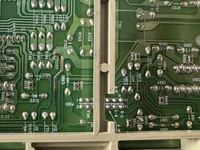
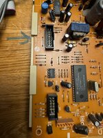
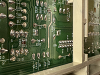
Has anyone looked into doing something like this and may already have some thoughts or maybe already know which pins are for what on the logic board?
I saw this cool hack which has all the details for the PSU.
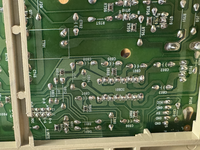
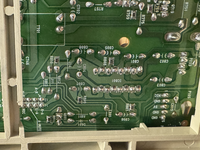
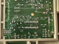
Guide : SFX PSU Conversion for Quadra 630/Performa 6200
Hello, Introduction : This is a quick guide on how I upgraded the PSU on my Performa 6200. This guide applies to all macs which share the same case (Quadra/LC/Performa 630, Performa/PowerMac 62XX/63XX) PowerSupplys inside this case are an afterthought. They are badly designed and the first...
Has anyone looked into doing something like this and may already have some thoughts or maybe already know which pins are for what on the logic board?
") . And yes, I just took that right out of the machine as I was going to junk it.
. And yes, I just took that right out of the machine as I was going to junk it.