• Updated 2023-07-12: Hello, Guest! Welcome back, and be sure to check out this follow-up post about our outage a week or so ago.

Overclock PowerBook 1400/117MHz to Cacheless 133MHz?

Snial

Well-known member
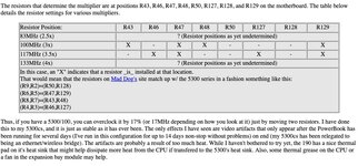
I have a PB1400/117MHz module. From what I gather, there was never a specific bin for 117MHz, nor 120MHz, only 100MHz and 133MHz. I went to the PowerPC 603e specifications document from Motorola/Freescale/NXP (https://www.nxp.com/docs/en/data-sheet/MPC603EEC.pdf). On page 24, the PLL_CFG is described.
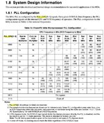
PowerPc603ePllCfg.jpg
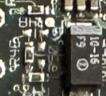
So, given the bus speed for the PowerBook 1400, we'd expect a 117MHz module to have setting 1110. It turns out that the 4 resistors on the underside correspond to that and in fact they do connect to the appropriate pins on the CPU itself.
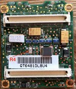
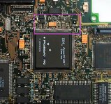
CpuModuleMod.jpg
So, the question is, how dodgy would it be to remove R4 and boost the CPU to 133MHz (with no cache)? From what I've read of the data sheet it shouldn't use up more power than an actual PowerBook 1400/133MHz + 128kB Cache, because there's no cache module to power!

From the data sheet: 100MHz= typical 3.2W to 133MHz=4.2W, 100MHz=4.0W to 133MHz=5.3W. So, you can tell it's approximately linear, because a 1.33x speed results in 1.31x power consumption, 117MHz will be approx 3.74W average and 4.68W max so going to 133MHz will cost another 0.62W max.

I might get a whole 7% to 13% performance improvement!!!
 

3lectr1cPPC

Well-known member
Ooh! Would be interesting to see if I could apply this to my 5300ce board, also 117MHz. If this ends up working for you I might to tempted.
 

Snial

Well-known member
Ooh! Would be interesting to see if I could apply this to my 5300ce board, also 117MHz. If this ends up working for you I might to tempted.
Good to get a bit of feedback! Do you have a picture of the CPU module? Is it obvious where the PLL_CFG resistors are?
 

3lectr1cPPC

Well-known member
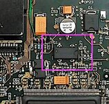
The 5300’s CPU is soldered, no card to be found. Here’s a picture of the board near it though, all I can see are resistor packs. Photo is of my spare 100MHz board, the 177 board is inside my 5300 that I don’t feel like taking apart.
AEFE7EC2-C507-467C-B055-8DA07E7B470F.jpeg
May be the blue ones on the right? I know nothing just about about overclocking.
 

Snial

Well-known member
The 5300’s CPU is soldered, no card to be found. Here’s a picture of the board near it though, all I can see are resistor packs. Photo is of my spare 100MHz board, the 177 board is inside my 5300 that I don’t feel like taking apart.
View attachment 59968
May be the blue ones on the right? I know nothing just about about overclocking.
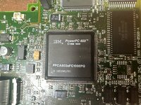
Sadly, I think that you won't be able to overclock the 5300/100. If you note the chip designation: PPCA603eFC100EPQ, I suspect the FC100 part is the processor frequency bin, which would be 100MHz. That means it shouldn't be overclocked. I'd need to check it out on the equivalent PowerPC 603e pdf, but for Motorola's PPC603e, the format is:

MPC 603 E XX XXX X X
Where XXX is the maximum CPU frequency.

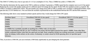
If you could clock it though, the PLL_CFG [3:0] signals are at pins 213, 211, 210, 208 respectively. You can see from the silk screen numbers: 60 and 61 on the bottom right; 120 and 121 on the top, right; 180 and 181 on the top left, then 240 is bottom left (hidden by the glare). I would guess the resistors just to the left of the orange 10µ16 cap(?) are those. It looks like one is fitted, then the next two aren't, then the last one is. However, the pattern doesn't quite make sense, because 1001 isn't valid, it should be 1000, because that's PLL x 3 so for a 33.3MHz Bus clock you get 100MHz. Either that or only the first 3 are valid and PLL_CFG[0] is implicitly 0. Then it would be possible to select 100MHz = 100[0], 117MHz 111[0] and 133MHz 101[0].

Except it would only work on your 117MHz 5300, which should have a different name for the chip. Even for the 117MHz chip I would be concerned about clocking it to 133MHz if there's no heat sink on the top, because the PowerBook 1400 series does have a heat sink, which implies it needs one (though the heat sink might be there, because the PPC 133MHz + Cache and above needed it).

In the late 1990s, I had a 100MHz PowerBook 5300 (grey-scale) with a 500MB drive and 40MB of RAM (8 Mobo + 32 Expansion). It also had an extra video card so I could use a second monitor in colour at about 832x624x8bpp or 1024x768x4bpp (which I used most of the time). I swapped my PowerMac 4400 + Duo 230 + Dock for it, because I didn't have the space for all that; I needed a PPC Mac for my MPhil and I needed a laptop. It was usable, but the HD was dodgy. It got me through to the end of my first thesis draft, and when I needed to do corrections, the iBook 300 had come down in price enough for me to afford it + an extra 64MB of RAM + an Airport card + a Zip 250 drive. It was a tangerine one, which was amazing!
 

3lectr1cPPC

Well-known member
It must be possible though because @k24a1 did it. Also pretty sure on my 5300ce board that the chip is marked 117, not 133 or anything else.

also it does have a makeshift heat sink, it’s a piece of metal that sits on top of it all when assembled.
 

Snial

Well-known member
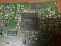
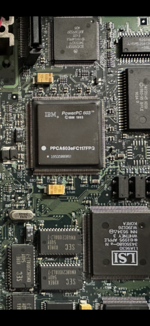
Found a photo of my 117 board, and it is marked as such:
That's really interesting. We can see that the PLL_CFG resistors for the 117MHz one are different to the 100MHz one. I can't tell what's written on my PPC603e chips, because there's some kind of thermal sponge on the surface. So, that's a bit more of a mystery, because maybe it means there really was a 117MHz bin (and that's odd, because the actual speed depends upon the bus speed x PLL and the chips wouldn't have been fabbed with the particular bus speed in mind, especially given the fact that no other 603e based systems had 117MHz (120MHz, 160MHz, 200MHz, 100MHz [6300?]).

Ppc603e100Pll_Cfg.jpg Ppc603e117Pll_Cfg.jpg
 

Snial

Well-known member
You mean on your PB1400 CPU module? Under the thermal sponge on a 117MHz card, the chip is labelled as 117…
That would imply that it certainly shouldn't be cranked up to 133MHz. The puzzle for me I guess is that the data sheets don't seem to mention 117MHz parts specifically, just 100MHz and 133MHz parts, even though, obviously @3lectr1cPPC 's 117MHz PB5300 does indeed have 117MHz written on the CPU!
 

Phipli

Well-known member
That would imply that it certainly shouldn't be cranked up to 133MHz.
"Shouldn't" is a strong word. It isn't so black and white and the chip label isn't that definitive.

Personally, I don't tend to overclock laptops for the most part.

You mention overclocking where a chip is rated higher than it is clocked? Even this isn't always a good thing where thermals are an issue - it is sometimes intentional to overspecify a chip so that it runs cooler in a confined space. The chip speed ratings assume a specific level of cooling and ambient, and where this isn't possible, "underclocking" can help keep temperatures in control. This is done from the factory in some instances, although there are also higher temperature grade chips (good trick, a while back I was happily buying some G3s on eBay because the were extended temperature range parts - they were labelled 300MHz, but we're effectively 400MHz parts because they were designed to do 300MHz in a high ambient temperature).

On the other hand, a 117MHz labelled chip in a laptop might happily run at 133MHz in England because it isn't in California - the ambient is much lower here.

But ultimately, the whole thing with overclocking is that it is completely individual chip specific. It means finding the specific limits of your device, while the manufacturer labelled parts by batch.

I had two 66MHz PPC upgrade cards at one point. I kept the one that happily runs at 80MHz all day, the other can't even boot at 80MHz without crashing. Identical cards, both repasted, both 66MHz chips.
 

Snial

Well-known member
"Shouldn't" is a strong word. It isn't so black and white and the chip label isn't that definitive.

Personally, I don't tend to overclock laptops for the most part.

You mention overclocking where a chip is rated higher than it is clocked? Even this isn't always a good thing where thermals are an issue - it is sometimes intentional to overspecify a chip so that it runs cooler in a confined space. The chip speed ratings assume a specific level of cooling and ambient, and where this isn't possible, "underclocking" can help keep temperatures in control. This is done from the factory in some instances, although there are also higher temperature grade chips (good trick, a while back I was happily buying some G3s on eBay because the were extended temperature range parts - they were labelled 300MHz, but we're effectively 400MHz parts because they were designed to do 300MHz in a high ambient temperature).

On the other hand, a 117MHz labelled chip in a laptop might happily run at 133MHz in England because it isn't in California - the ambient is much lower here.

But ultimately, the whole thing with overclocking is that it is completely individual chip specific. It means finding the specific limits of your device, while the manufacturer labelled parts by batch.

I had two 66MHz PPC upgrade cards at one point. I kept the one that happily runs at 80MHz all day, the other can't even boot at 80MHz without crashing. Identical cards, both repasted, both 66MHz chips.
Thanks for redressing the balance!

It's worth pointing out my hypocrisy in that my reply on the Unpopular Mac Opinions where I listed people boosting the performance of their Macs when presumably the reason why they bought the retro Mac was because of the experience of that contemporary tech!

Hey, on a side note, have you figured out what to do with the DIY LC expansion board? I sometimes wonder how hard it would be to make a Macduino and then add some Arduino shields (use GCC to compile sketches). It's probably pretty dumb for anything but simple shields as you'd have to port the low-level I/O code.
 

Phipli

Well-known member
Hey, on a side note, have you figured out what to do with the DIY LC expansion board? I sometimes wonder how hard it would be to make a Macduino and then add some Arduino shields (use GCC to compile sketches). It's probably pretty dumb for anything but simple shields as you'd have to port the low-level I/O code.
The next parts arrived today, I'm not in a hurry. Lots of other things to do. I shared the photo because I was happy the connectors arrived and we're better quality than expected (I know that sounds silly, but I've been forced to buy cheap lately, so some stuff arrives and... Is junk).

I'll document it when I have something usable, or perhaps make a prototyping board with buffers and address decoding onboard.
 

Snial

Well-known member
The next parts arrived today, I'm not in a hurry. Lots of other things to do. I shared the photo because I was happy the connectors arrived and we're better quality than expected (I know that sounds silly, but I've been forced to buy cheap lately, so some stuff arrives and... Is junk).

I'll document it when I have something usable, or perhaps make a prototyping board with buffers and address decoding onboard.
Well, it sounds really intriguing! Hope you have fun!
 
Top